44x/EN TS/Hb6
1-10 MiCOM P40 Agile
6 ERROR CODE DURING OPERATION
The relay performs continuous self-checking, if an error is detected then an error message
will be displayed, a maintenance record will be logged and the relay will reset (after a 1.6
second delay). A permanent problem (for example due to a hardware fault) will generally be
detected on the power up sequence, following which the relay will display an error code and
halt. If the problem was transient in nature then the relay should reboot correctly and
continue in operation. The nature of the detected fault can be determined by examination of
the maintenance record logged.
There are also two cases where a maintenance record will be logged due to a detected error
where the relay will not reset. These are detection of a failure of either the field voltage or the
lithium battery, in these cases the failure is indicated by an alarm message, however the
relay will continue to operate.
If the field voltage is detected to have failed (the voltage level has dropped below threshold),
then a scheme logic signal is also set. This allows the scheme logic to be adapted in the
case of this failure (for example if a blocking scheme is being used).
In the case of a battery failure it is possible to prevent the relay from issuing an alarm using
the setting under the Date and Time section of the menu. This setting ‘Battery Alarm’ can be
set to 'Disabled' to allow the relay to be used without a battery, without an alarm message
being displayed.
Error codes (as reported by the relay via the front panel or in the Maintenance Records) can
offer a considerable amount of information about the source of the error.
The Hex Code is reported on the front user interface of the relay immediately prior to a
reboot sequence. If this code could not be observed, use the Maintenance Records section
of the View Records column to display the corresponding Decimal Code.
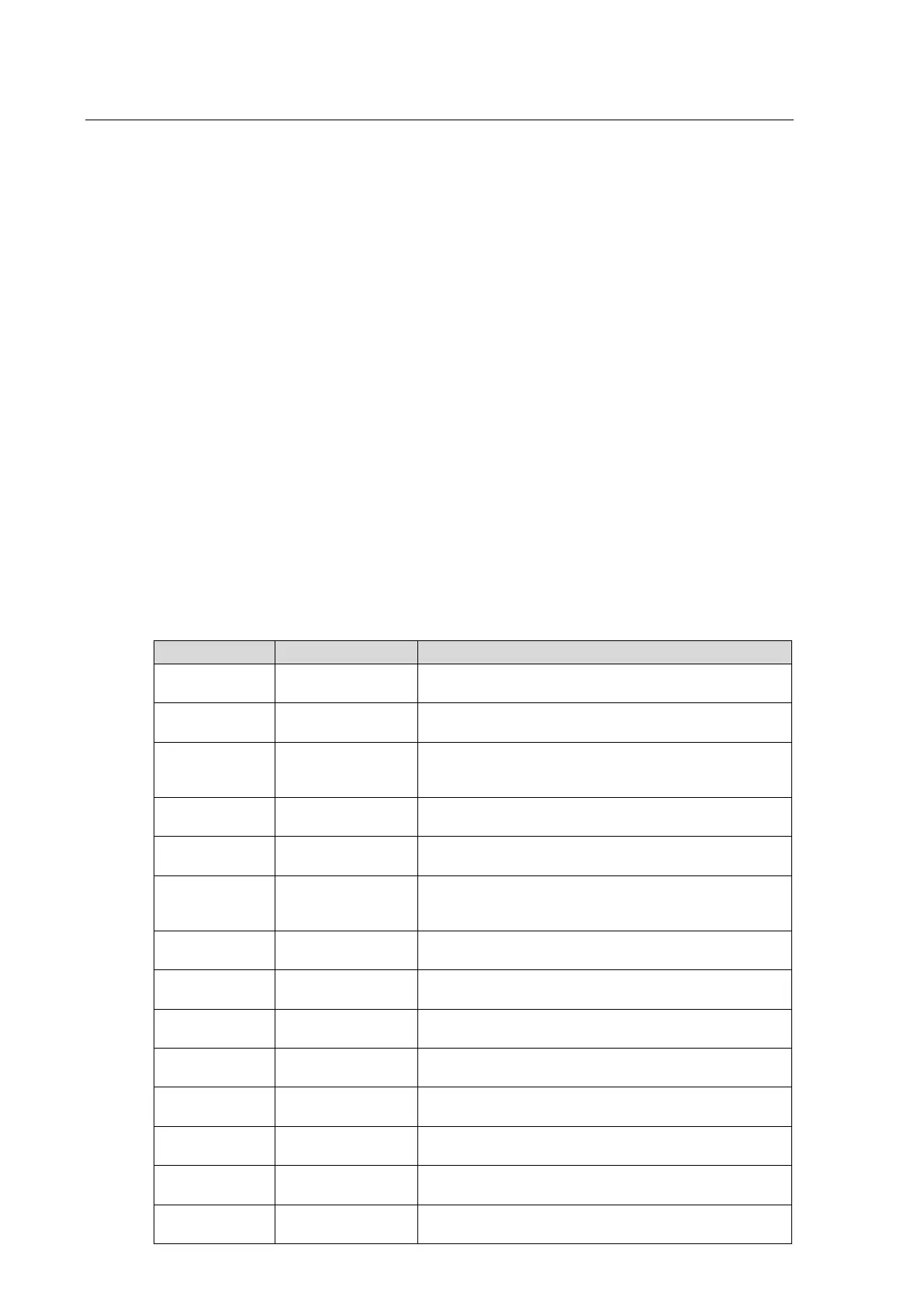
Hex Code Decimal Code Meaning
0x0C0D0000 202178560
An error has been found in the acquisition process. Check
the input boards and opto-input boards
0x0C1600C0 202768576
An error has been found in the output relay board. Check
the output relay boards.
0x0C140001 202637313
The serial driver failed to initialise properly. Check the
serial port hardware on the power supply board and the
main processor board.
0x0C140002 202637314
The LCD driver failed to initialise properly. Check the LCD
on the main processor board.
0x0C140003 202637315
The Flash memory driver failed to initialise properly. Check
the Flash memory on the main processor board.
0x0C140004 202637316
The date and time driver failed to initialise properly. Check
the real-time clock and battery-backed SRAM on the main
processor board.
0x0C140005 202637317
The acquisition software failed to initialise properly. Check
the input boards and opto-input boards
0x0C140006 202637318
The relay software failed to initialise properly. Check the
input boards and opto-input boards
0x0C140007 202637319
The recorder software failed to initialise properly. Check the
SRAM memory backup on the main processor board
0x0C140008 202637320
The database failed to initialise properly. Check the
EEPROM on the main processor board.
0x0C140009 202637321
The
database took too long to commit a change. Check the
EEPROM on the main processor board.
0x0C14000A 202637322
The IRIG-B driver failed to initialise properly. Check the
IRIG-B interface hardware on the IRIG-B board.
0x0C160010 202768400
The continuous self-
checks have found an error in the RAM
bus. Check the RAM on the main processor board.
0x0C160011 202768401
The continuous self-
checks have found an error in the RAM
block. Check the RAM on the main processor board.
 Loading...


