b6
CM) 9-30
MiCOM P40 Agile P442, P444
5.3.1.3 Check and test of the starting characteristics
In this part – tests are described with the default parameters
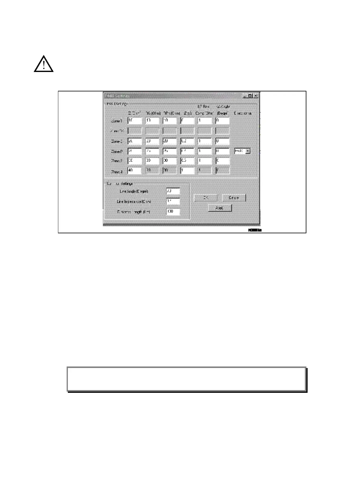
Open the MiCOM characteristics file If no changes have been made, the following values are
obtained (Z-graph screen):
Figure 12:
Control of single-phase fault characteristic’
CAUTION: If different K0 are used – SEE SECTION 5.3.1.2
1. Energise MiCOM P44x with a healthy three-phase system (without any unbalanced
condition) with a load (during a minimum time of 500 ms). This is to:
Enable the use of the Delta algorithms
Avoid the start of the SOTF logic
2. Reduce the current value to obtain a relation between V and I following the appended
table (for Rlim – phase-shift at 0°, for Z limit – phase-shift corresponding to Z1 (in
multiphase default) or corresponding to 2Z1+Z0 (in single fault).
3. Check that the tripping order (DDB: Any trip / Any Trip A/ Any Trip B/ Any Trip C – see
DDB description) is transmitted when the concerned zone time-delay expires (for a
distance scheme with transmission and all distance trip logic see the Application
Notes chapter.
Note: The DDB signal any Trip A is an OR gate between
Ext Trip A
Int Trip A
4. See also the test report model (end of this section).
5. Check also in the PSL (programmable scheme logic) the trip command addresses
(any Trip is linked by default to the relay 7).
By default: see the wiring diagram (for assignment of inputs/outputs).
Useful tip: - To check the logic level of internal datas (DDB cells), all or some of the 8 red
LEDs on the front panel could be assigned using the PSL.
 Loading...


