-20
MiCOM P40 Agile P442, P444
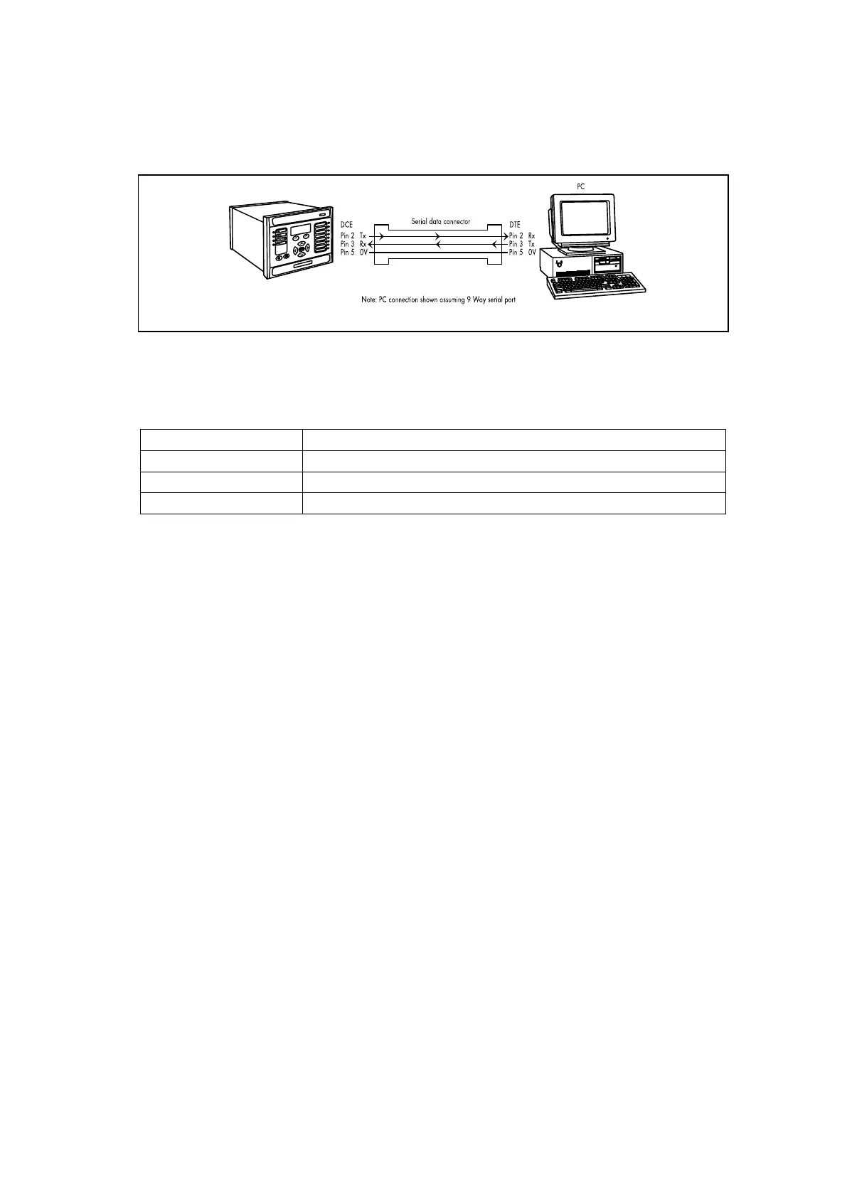
communication is connecting Tx to Tx and Rx to Rx. This could happen if a ‘cross-over’
serial connector is used, i.e. one that connects pin 2 to pin 3, and pin 3 to pin 2, or if the PC
has the same pin configuration as the relay.
Figure 8: PC – relay signal connection
Having made the physical connection from the relay to the PC, the PC’s communication
settings must be configured to match those of the relay. The relay’s communication settings
for the front port are fixed as shown in the table below:
Protocol Courier
Baud rate 19,200 bits/s
Courier address 1
Message format 11 bit - 1 start bit, 8 data bits, 1 parity bit (even parity), 1 stop bit
The inactivity timer for the front port is set at 15 minutes. This controls how long the relay will
maintain its level of password access on the front port. If no messages are received on the
front port for 15 minutes then any password access level that has been enabled will be
revoked.
1.10 Introduction to the Settings Application Software
The settings application software used in this range of IEDs is called MiCOM S1 Agile. It is a
collection of software tools, which is used for managing all aspects of the IEDs. This chapter
provides a brief summary of each software tool. Further information is available in the Help
system and in the Settings Application Software Guide P40-M&CR-UG-EN-n, where n is the
latest version of the settings application software.
The software allows you to edit device settings and commands for General Electric’s range
of IEDs. It is compatible with Windows XP, Windows Vista and Windows 7 operating
systems.
It also enables you to manage the MiCOM devices in your system. You can build a list of
devices and organize them in the same way as they physically exist in a system. Parameters
can be created and uploaded for each device, and devices can be supervised directly.
It also includes a Product Selector tool. This is an interactive product catalogue, which
makes it easier to choose the right device for each application.
1.10.1 Getting Started
S1 Agile allows you to create a model of a protection system which simulates a real-world
protection system. You can add substations, bays, voltage levels and devices to the system.
First you need to download the data models for the devices in the system. Then you can
either create a new system or open an existing system. You can connect to an IED either
directly through the front port or to an IED in the system model. You can then send or extract
settings. You can also extract PSL, DNP3, Events or Disturbance Record files.
If there is no default system, use Quick Connect to automatically create one. If a system is
no longer needed, right-click it and select Delete to permanently delete it. Systems are not
opened automatically. To change this, select Options then Preferences then check the
checkbox Reopen last System at start-up.
 Loading...


