44x/EN AP/Hb6
-102 MiCOM P40 Agile
SBE
F T
r
ip
SBE
F
O
ve
rc
u
rren
t
C
TS
B
lo
ck
SBE
F T
ri
p
P0484ENa
SBEF
T
im
er
B
lo
ck
SBE
F S
ta
r
t
I
DM
T/
D
T
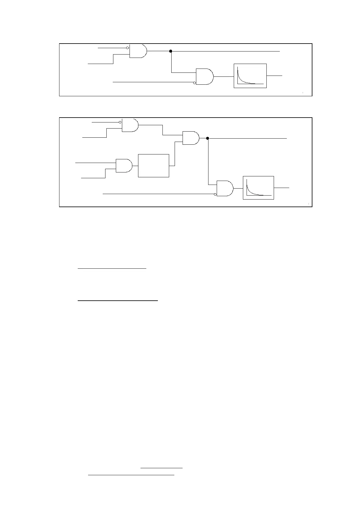
Figure 71: Logic without directionality
SBEF Trip
SBEF
Overcurrent
CTS Block
P0533ENa
SBEF Timer Block
SBEF Start
Vx > Vs
Ix > Is
Slow VTS
Block
IDMT/DT
Directional
Check
Figure 72: Logic with directionality
4.7.2 Directional Earth Fault Protection (DEF)
The method of directional polarising selected is common to all directional earth fault
elements, including the channel-aided element. There are two options available in the relay
menu:
• Zero sequence polarising - The relay performs a directional decision by comparing the
phase angle of the residual current with respect to the inverted residual voltage: (–
Vres = –(Va + Vb + Vc)) derived or measured by the relay. The application of zero
sequence polarising is detailed in section 1.1.2.1.
• Negative sequence polarising - The relay performs a directional decision by
comparing the phase angle of the derived negative sequence current with respect to
the derived negative sequence voltage. The application of negative sequence
polarising is detailed in section 1.1.2.2.
Note: Even though the directional decision is based on the phase relationship of I
2
with respect to V
2
, the operating current quantity for DEF elements remains
the residual current.
4.7.2.1 Application of Zero Sequence Polarising
This is the conventional option, applied where there is not significant mutual coupling with a
parallel line, and where the power system is not solidly earthed close to the relay location. As
residual voltage is generated during earth fault conditions, this quantity is commonly used to
polarise DEF elements. The relay internally derives this voltage from the 3 phase voltage
input which must be supplied from either a 5-limb or three single phase VT’s. These types of
VT design allow the passage of residual flux and consequently permit the relay to derive the
required residual voltage. In addition, the primary star point of the VT must be earthed. A
three limb VT has no path for residual flux and is therefore incompatible with the use of zero
sequence polarising.
The required characteristic angle (RCA) settings for DEF will differ depending on the
application. Typical characteristic angle settings are as follows:
• Resistance earthed systems generally use a 0° RCA setting. This means that for a
forward earth fault, the residual current is expected to be approximately in phase with
the inverted residual voltage (-Vres).
• When protecting solidly-earthed distribution systems or cable feeders, a -45° RCA
setting should be set.
 Loading...


