P44x/EN AP/Hb
MiCOM P40 Agile P442, P444
(AP) 5-
4.6.2 Setting example
The following information was recorded by the relay during commissioning:
• I
full load
= 1000A
• I
2
= 100A
therefore the quiescent I2/I1 ratio is given by:
• I
2
/I
1
= 100/1000 = 0.1
To allow for tolerances and load variations a setting of 200% of this value may be typical:
Therefore set I2/I1 = 0.2
Set I2/I1 Time Delay = 60 s to allow adequate time for short circuit fault clearance by time
delayed protections.
4.7 Directional and non-directional earth fault protection
4.7.1 Setting guidelines
The MiCOM P44x negative sequence overcurrent protection elements include four
thresholds. The first and the second thresholds can be set as DT or IDMT trip delay time.
The curves are the same as for the directional and non directional overcurrent protection.
Note that the elements are set in terms of residual current, which is three times the
magnitude of the zero sequence current (Ires = 3I
0
). The IDMT time-delay characteristics
available for the IN>1 element, and the grading principles used will be as per the phase fault
overcurrent elements.
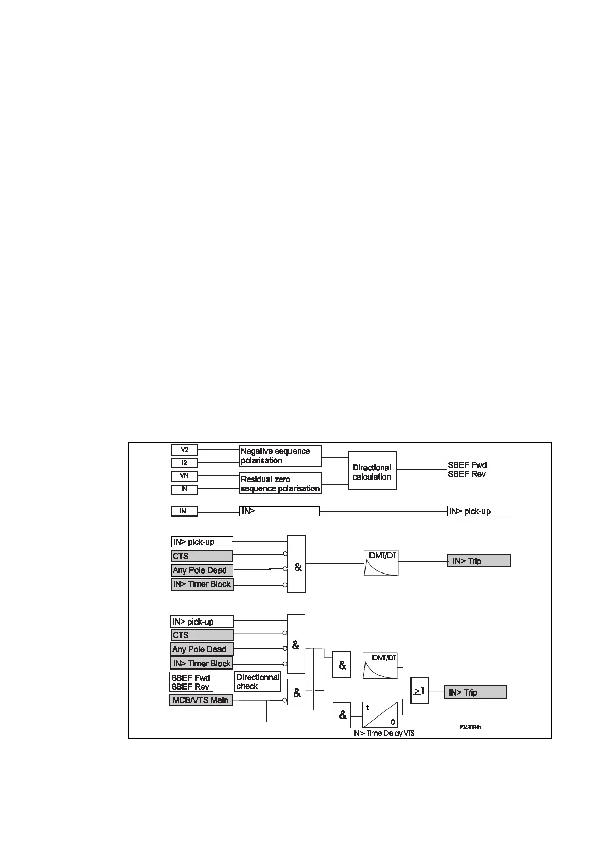
To maintain protection during periods of VTS detected failure, the relay allows an IN> Time
Delay VTS to be applied to the IN>1 and IN>2 elements. On VTS pickup, both elements are
forced to have non-directional operation, and are subject to their revised definite time-²delay.
Figure 70: SBEF calculation & logic
 Loading...


