P44x/EN CM/Hb
MiCOM P40 Agile P442, P444
(CM) 9-
6 ON-LOAD CHECKS
Remove all test leads and temporary shorting leads, and replace any external wiring that has
been removed to allow testing.
If it has been necessary to disconnect any of the external wiring from the relay in order to
perform any of the foregoing tests, it should be ensured that all connections are replaced in
accordance with the relevant external connection or scheme diagram.
The following on-load measuring checks ensure the external wiring to the current and
voltage inputs is correct but can only be carried out if there are no restrictions preventing the
energisation of the plant being protected.
6.1 Voltage Connections
Using a multimeter measure the voltage transformer secondary voltages to ensure they are
correctly rated. Check that the system phase rotation is correct using a phase rotation
meter.
Compare the values of the secondary phase voltages with the relay’s measured values,
which can be found in the MEASUREMENTS 1 menu column.
If cell [0D02: MEASURE’T SETUP, Local Values] is set to ‘Secondary’, the values displayed
on the relay should be equal to the applied secondary voltage. The relay values should be
within 1% of the applied secondary voltages. However, an additional allowance must be
made for the accuracy of the test equipment being used.
If cell [0D02: MEASURE’T SETUP, Local Values] is set to ‘Primary’, the values displayed on
the relay should be equal to the applied secondary voltage multiplied by the corresponding
voltage transformer ratio set in the ‘VT & CT RATIOS’ menu column (see Table 14). Again
the relay values should be within 1% of the expected value, plus an additional allowance for
the accuracy of the test equipment being used.
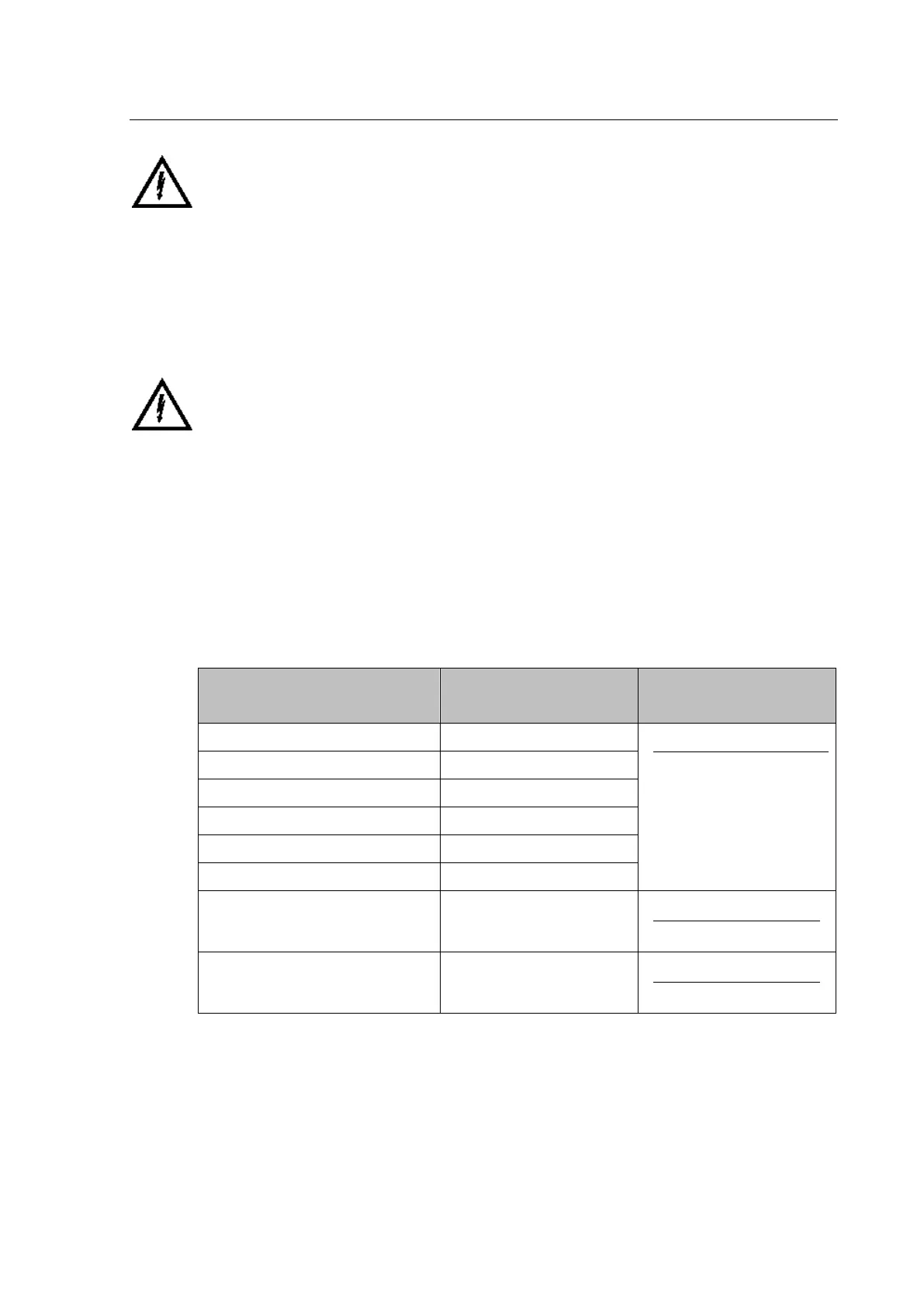
Voltage
Cell in MEASUREMENTS 1
column (02)
Corresponding VT Ratio
(in ‘VT and CT RATIO
column (0A) of menu)
VAB [0214: VAB Magnitude]
0A07:Phase CT Primary
0A08:Phase CT Sec'y
VBC [0216: VBC Magnitude]
VCA [0218: VCA Magnitude]
VAN [021A: VAN Magnitude]
VBN [021C: VBN Magnitude]
VCN [021E: VCN Magnitude]
VCHECKSYNC [022B: C/S Voltage Mag]
0A03:C/SVT Primary
0A04:C/SVT Sec'y
VN measured [0222: VN Mag]
0A03:C/SVT Primary
0A04:C/SVT Sec'y
Table 14 - Measured Voltages and VT Ratio Settings
 Loading...


