P44x/EN CM/Hb
MiCOM P40 Agile P442, P444
(CM) 9-
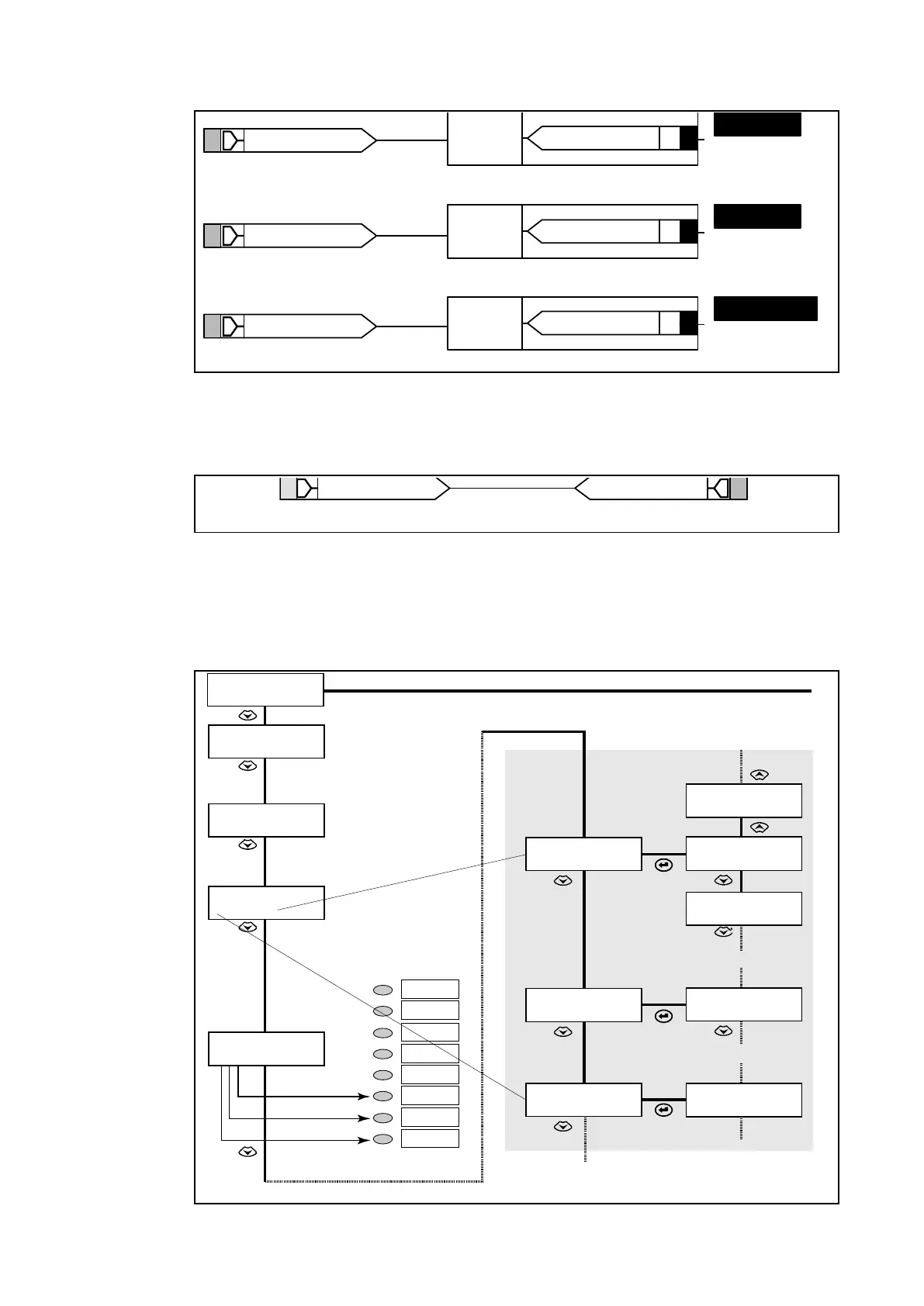
Z1
Z2
T2
DDB #191
DDB #193
DDB #198
LED 8
DDB #069
LED 7
DDB #070
LED 8
DDB #071
Latching
Z1
Z2
T2
Latching
Non-
Latching
P3018ENa
Figure 13:
If the LEDs are latched, the reset latch could be enabled by a dedicated PSL, to avoid
needless keypad access during the tests:
Any Start
DDB #253
Reset Latches
DDB #118
P3019ENa
Figure 14:
Useful tip: - To check the logic level of internal data (DDB cells), monitor bit control can be
used in "commissioning Test / Opto / Relay / Test port status / Led status / Monitor bit 1 to bit
8". Any cells of the DDB can be assigned and then displayed as 1 of the 8 bits (see User
Tools).
COMMISSION
TESTS
Opto I/P Status
0000000000100
LED Status
00000000
Relay O/P Status
0000000000100
Test port Status
00000000
Monitor Bit 1
64
Monitor Bit 1
64
Monitor Bit 1
64
Monitor Bit 1
64
Monitor Bit 2
65
Monitor Bit 8
71
Monitor Bit 2
65
Monitor Bit 8
71
P3020ENa
Figure 15: LCD menu for a control of an input/output / monitor bits check
 Loading...


