tenance
P44x/EN MT/Hb
P444 (MT) 10-
1.3.2.2 Replacement of an optional (IRIG-B, Ethernet…) board
To replace a faulty board, disconnect all connections at the rear of the relay.
Depending on the model number of the relay, the optional board may have connections for
IRIG-B signals, IEC 60870-5-103 (VDEW) communications, etc.
To replace a faulty board, disconnect all connections at the rear of the relay.
The module is secured in the case by two screws accessible from the rear of the relay, one
at the top and another at the bottom, as shown in Figure 4. Remove these screws carefully
as they are not captive in the rear panel of the relay.
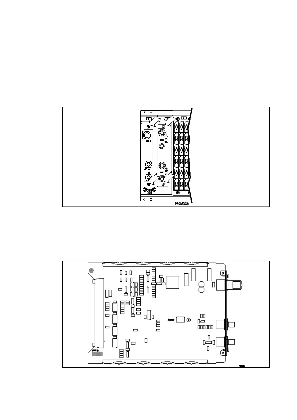
Figure 4 - Location of Securing Screws for optional Boards
Gently pull the board forward and out of the case.
To help identify that the correct board has been removed, Figure 5 shows the layout of the
IRIG-B board with both IRIG-B and IEC 60870-5-103 options fitted (ZN0007 003). The other
versions (ZN0007 001 and ZN0007 002) use the same PCB layout but with less components
fitted.
Figure 5 - Typical IRIG-B Board
The replacement PCB should be carefully fitted into the appropriate slot, ensuring that it is
pushed fully back on to the rear terminal blocks and the securing screws are re-fitted.
Reconnect all connections at the rear of the relay.
 Loading...


