44x/EN AP/Hb6
-54 MiCOM P40 Agile
P3065ENa
Figure 31: Main protection in the BOP Z1 scheme
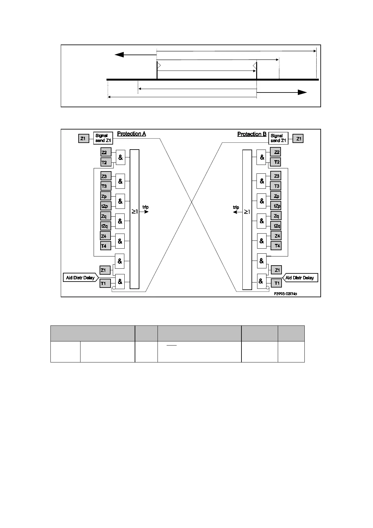
Figure 32: Logic diagram for the BOP Z1 scheme
Trip logic:
IEC Standard
Carrier
Send
Trip Logic Application
User
setting
448.15.14 BOR1 or BOP Z4
Z1. CR .T1.
‘Aid Dist Delay’
+ Z2.T2 + Z3.T3...
Z1 > ZL BOP Z1
3.2.1.4.2 Blocking Overreach Protection with Overreaching Zone 2 (BOP Z2)
Figure 33 shows the zone reaches, and Figure 34 the simplified scheme logic. The signalling
channel is keyed from operation of the reverse zone 4 elements of the relay. If the remote
relay has picked up in zone 2, then it will operate after the aided distribution time-delay if no
block is received.
Send logic: Reverse Zone 4
Trip logic: Zone 2, plus Channel NOT Received, delayed by ‘Aid Dist Delay’.
 Loading...


