P44x/EN CM/Hb
MiCOM P40 Agile P442, P444
(CM) 9-
4.2.9.2 Modbus Communications
Connect a portable PC running the appropriate Modbus Master Station software to the
relay’s RS485 port via a RS485 to RS232 interface converter. The terminal numbers for the
relay’s RS485 port are given in Table 7.
Ensure that the relay address, baud rate and parity settings in the application software are
set the same as those in cells [0E03: COMMUNICATIONS, Remote Address], [0E06:
COMMUNICATIONS, Baud Rate] and [0E07: COMMUNICATIONS, Parity] of the relay.
Check that communications with this relay can be established.
4.2.9.3 IEC 60870-5-103 (VDEW) Communications
If the relay has the optional fibre optic communications port fitted, the port to be used should
be selected by setting cell [0E09: COMMUNICATIONS, Physical Link] to ‘Fibre Optic’ or
‘RS485’.
IEC 60870-5-103/VDEW communication systems are designed to have a local Master
Station and this should be used to verify that the relay’s fibre optic or RS485 port, as
appropriate, is working.
Ensure that the relay address and baud rate settings in the application software are set the
same as those in cells [0E03: COMMUNICATIONS, Remote Address] and [0E06:
COMMUNICATIONS, Baud Rate] of the relay.
Check that, using the Master Station, communications with the relay can be established.
4.2.10 Current Inputs
This test verifies that the accuracy of current measurement is within the acceptable
tolerances.
All relays will leave the factory set for operation at a system frequency of 50 Hz. If operation
at 60 Hz is required then this must be set in cell [0009: SYSTEM DATA, Frequency].
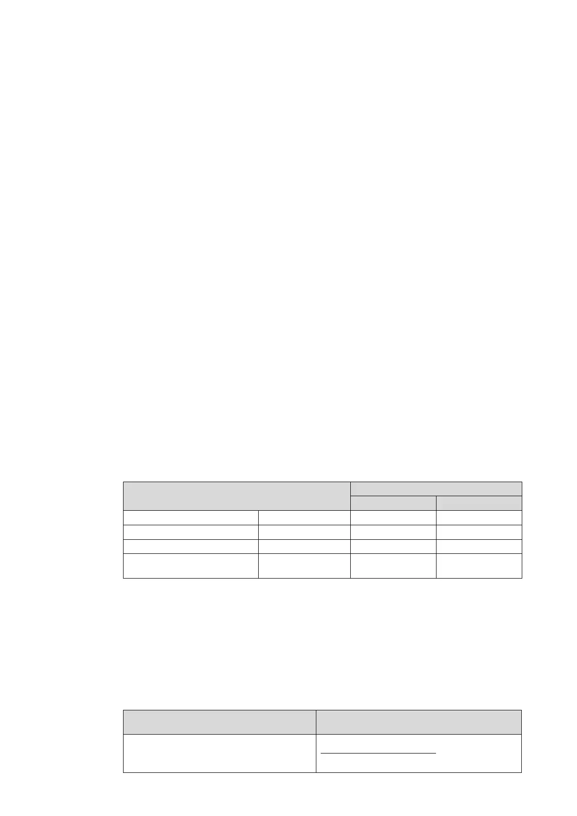
Apply current equal to the line current transformer secondary winding rating to the each
current transformer input of the corresponding rating in turn, checking its magnitude using a
multimeter. Refer to Table 8 for the corresponding reading in the relay’s MEASUREMENTS
1 column and record the value displayed.
Cell in MEASUREMENTS 1 column (02)
[0201: IA Magnitude] C3-C2 C1-C2
[0203: IB Magnitude] C6-C5 C4-C5
[0205: IC Magnitude] C9-C8 C7-C8
[022F IM Magnitude] or [0209: IN
Mag]
C12-C11 C10-C11
Table 8 - Current Input Terminals
The measured current values on the relay will either be in primary or secondary Amperes. If
cell [0D02: MEASURE’T SETUP, Local Values] is set to ‘Primary’, the values displayed on
the relay should be equal to the applied current multiplied by the corresponding current
transformer ratio set in the ‘VT and CT RATIOS’ menu column (see Table 9). If cell [0D02:
MEASURE’T SETUP, Local Values] is set to ‘Secondary’, the value displayed should be
equal to the applied current.
The measurement accuracy of the relay is ±1%. However, an additional allowance must be
made for the accuracy of the test equipment being used.
Cell in MEASUREMENTS 1 column (02)
Corresponding CT Ratio
(in ‘VT and CT RATIO column (0A) of menu)
[0201: IA Magnitude]
[0203: IB Magnitude]
[0205: IC Magnitude]
0A07:Phase CT Primary
0A08:Phase CT Sec'y
 Loading...


