P44x/EN ST/Hb
P442, P444 (ST) 4-
2.9 Aided Directional Earth Fault (DEF) protection schemes (“Aided D.E.F” menu)
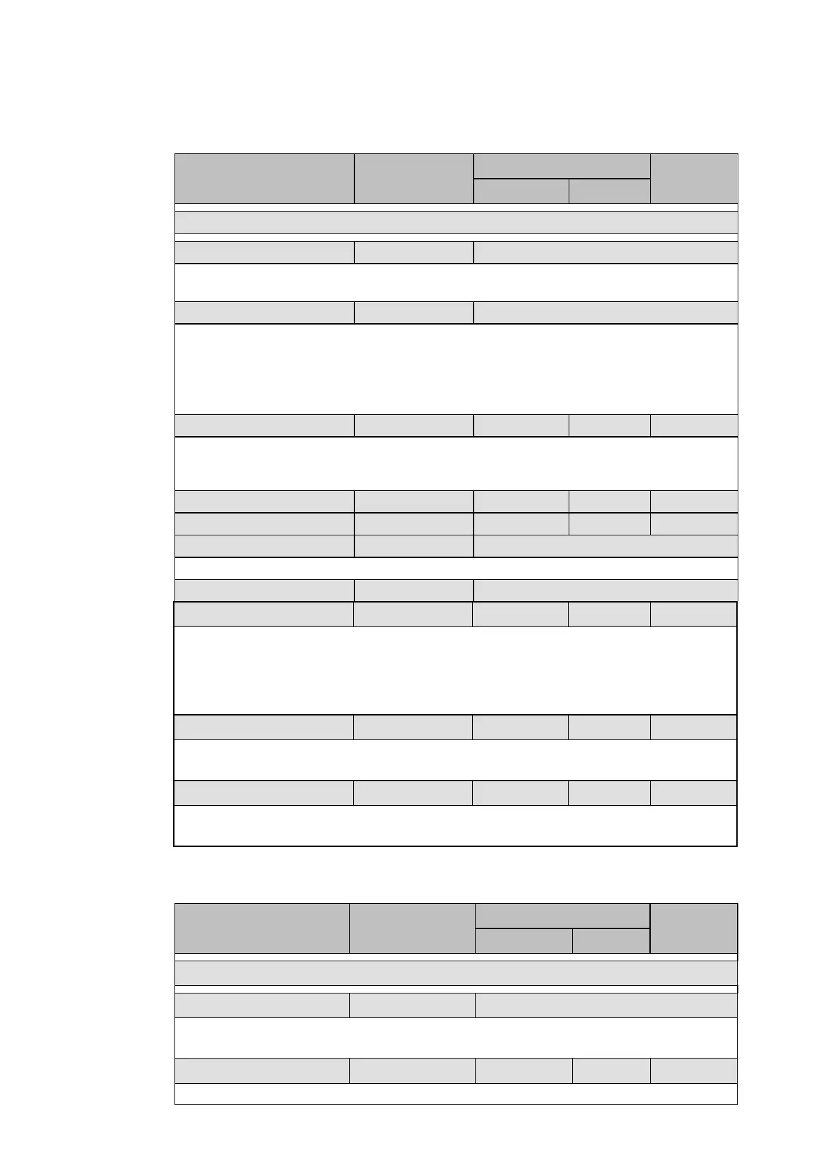
The relay has aided scheme settings as shown in the following table:
Menu text Default setting
Setting range
Step size
Min Max
GROUP 1 – AIDED D.E.F.
Aided DEF Status Enabled Disabled, Enabled
To enable (activate) or disable (turn off) the Directional Earth Fault Element that is used in
an aided scheme.
Polarisation Zero Sequence Zero Sequence, Negative Sequence
Setting that defines the method of DEF polarisation. Either zero, or negative sequence
voltage can be taken as the directional reference.
The applications of zero sequence and negative sequence polarisation are described in
chapter P44x/EN AP, section Directional Directional and non directional Earth Fault
Protection).
V> Voltage Set 1 V 0.5 V 20 V 0.01 V
The V> threshold defines the minimum residual voltage required to enable the aided DEF
directional decision. A residual voltage measured below this setting would block the
directional decision, and so there would be no tripping from the scheme.
IN Forward 0.1 × In 0.05 × In 4 × In 0.01 × In
Time Delay 0 s 0 s 10 s 0.1 s
Scheme Logic Shared Shared, Blocking, Permissive
To select shared, blocking or permissive scheme logic.
Tripping Three Phase Three Phase, Single Phase
Tp 2 ms 0 ms 1s 2 ms
Aid Dist Delay (if blocking scheme not shared)
Transmission time in blocking scheme. The Aided distribution time-delay (in the case of a
blocking scheme covering the transmission time) settings will appear in the relay menu.
Further customising of distance schemes can be achieved using the Programmable
Scheme Logic to condition send and receive logic.
IN Rev Factor 0,6 0 1 0.1
‘IN Rev Factor’ enhances the sensitivity for the residual current in case of reverse fault (for
instance to create a faster blocking logic scheme).
Block. Time Add. 0 0 10s 0.15s
“Block. Time Add.” is an additional time-delay, set to extend a pole dead or convergence
detection.
2.10 Thermal overload (“Thermal overload” menu)
The following table shows the menu settings for the thermal protection element:
Menu text Default setting
Setting range
Step size
Min Max
GROUP 1 – THERMAL OVERLOAD
Thermal Char Single Disabled, Single, Dual
Thermal characteristic setting. Available choices are: ‘Disabled”, ‘Single’ (for line and cable
protection) and ‘Dual’ (for oil-filled transformers with natural air cooling protection).
Thermal Trip
1Ιn 0.08Ιn 3.2Ιn 0.01Ιn
Sets the full load current (Ι
FLC
) allowed and the pick-up threshold of the thermal
 Loading...


