P44x/EN AP/Hb
MiCOM P40 Agile P442, P444
(AP) 5-
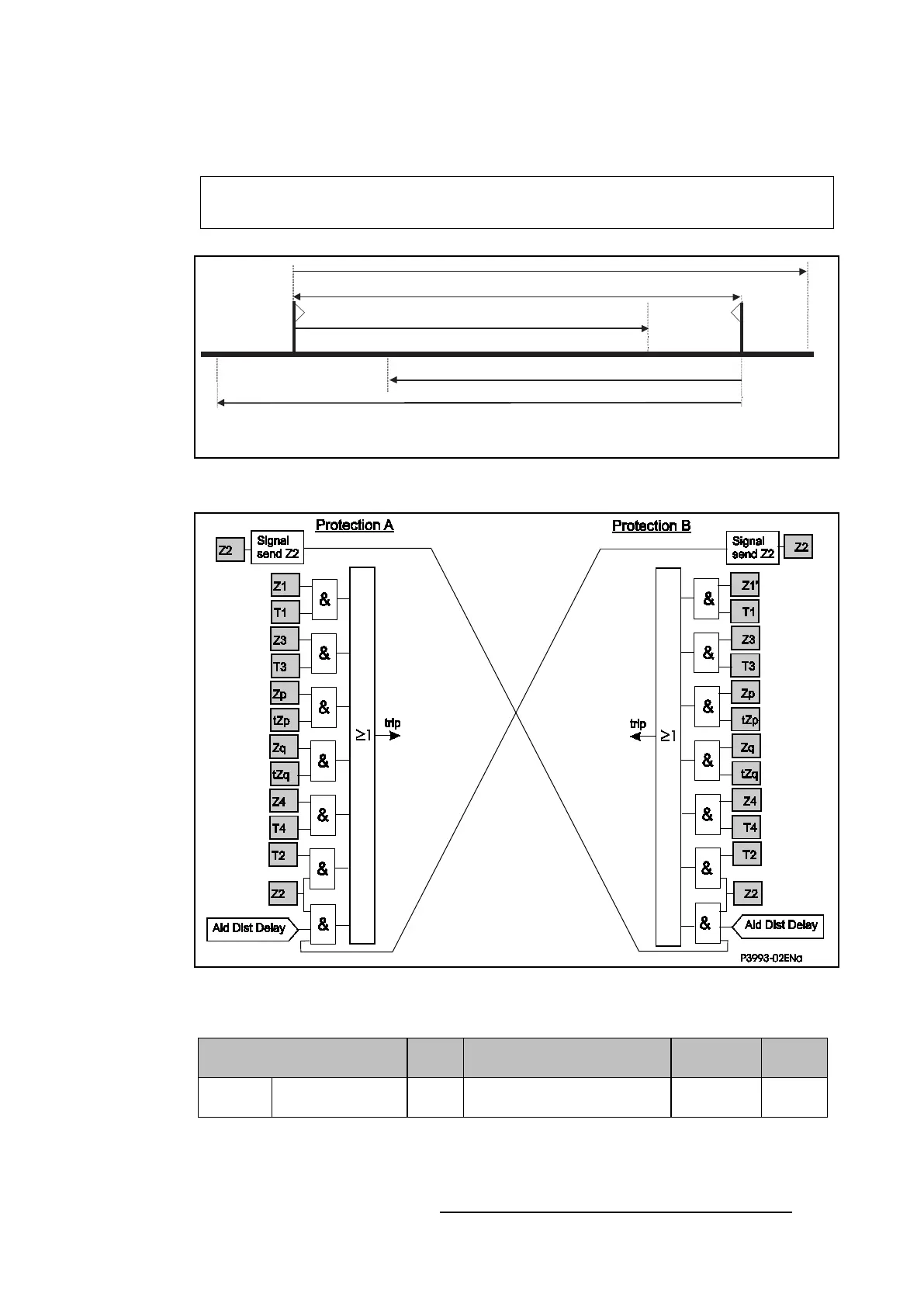
The signaling channel is keyed from operation of zone 2 elements of the relay. If the remote
relay has picked up in zone 2, then it will operate with Transmission Time (‘Distance
schemes / Aid Dist Delay’) delay on reception of the permissive signal.
Send logic: Zone 2
Permissive trip logic: Zone 2 plus Channel Received.
P 5 XX30 4 a
ZL
Z1A
A
B
Z1B
Z2A
Z2B
Figure 27: Main protection in the POP Z2 scheme
Figure 28: Logic diagram for the POP Z2 scheme
Trip logic:
IEC Standard
Carrier
Trip Logic Application
User
PUR2 or POR2 Z2
Z2.CR.’Aid Dist Delay’ + Z1.T1 + Z2.T2
+ Z3.T3...
Z1 = 80% ZL POP Z2
3.2.1.3.2 Permissive Overreach Protection with Overreaching Zone 1 (POP Z1)
Figure 29 shows the zone reaches, and Figure 30 the simplified scheme logic. The signalling
channel is keyed from operation of zone 1 elements set to overreach the protected line. If the
remote relay has picked up in zone 1, then it will operate with no additional delay upon
receipt of this signal. The POP Z1 scheme also uses the reverse looking zone 4 of the relay
 Loading...


