44x/EN ST/Hb6
-28 MiCOM P40 Agile
2.7 Broken conductor detection
The following table shows the relay menu for the Broken Conductor protection, including the
available setting ranges and factory defaults:
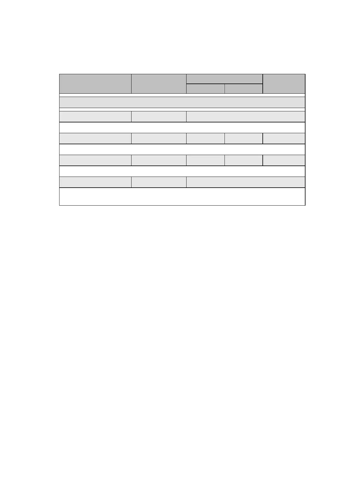
Menu text Default setting
Step size
GROUP 1 – BROKEN CONDUCTOR
Broken Conductor Enabled Enabled, Disabled
Setting that enables or disables the broken conductor protection.
I2/I1 0.2 0.2 1 0.01
Setting to determine the pick-up level of the negative to positive current ratio.
I2/I1 Time Delay 60 s 0 s 100 s 1 s
Setting for the function operating time-delay.
I2/I1 Trip Disabled Enabled, Disabled
Enables or disables the negative to positive current ratio protection. If disabled, only a
Broken Conductor Alarm is possible.
2.8 Directional and non-directional earth fault protection (“Earth fault O/C” menu)
The ‘Earth fault O/C’ menu is displayed when ‘CONFIGURATION/Earth Fault Prot’ cell is set
to “Earth Fault O/C”.
The following elements of earth fault protection are available, as follows:
• IN> element – Channel aided directional earth fault protection;
• IN>1 element – Directional or non-directional protection, definite time
(DT) or IDMT time-delayed.
• IN>2 element – Directional or non-directional, DT and IDMT delayed.
• IN>3 element – Directional or non-directional, DT delayed.
• IN>4 element – Directional or non-directional, DT delayed.
The MiCOM P44x earth fault protection elements include four thresholds. The first and the
second thresholds can be set as DT or IDMT trip delay time. The curves are the same as for
the directional and non directional overcurrent protection (see section 2.4).
The IN> element may only be used as part of a channel-aided scheme, and is fully described
in the Aided DEF section of the Application Notes.
The IN>1, IN>2, IN>3 and IN>4 backup elements always trip three pole, and have an
optional timer hold facility on reset, as per the phase fault elements. (The IN> element can
be selected to trip single and/or three pole).
All Earth Fault overcurrent elements operate from a residual current quantity which is derived
internally from the summation of the three phase currents.
These current thresholds are activated as an exclusive choice with Zero sequence Power
Protection:
The following table shows the relay menu for the Earth Fault protection, including the
available setting ranges and factory defaults.
 Loading...


