P44x/EN AP/Hb
MiCOM P40 Agile P442, P444
(AP) 5-1
4.9.1 Time constant characteristic
4.9.1.1 Single time constant characteristic
This characteristic is the recommended typical setting for line and cable protection. The
thermal time characteristic is given by:
exp(-t/τ) = (Ι
2
– (k.Ι
FLC
)
2
) / (Ι
2
– Ι
P
2
)
Where:
t = Time to trip, following application of the overload current, Ι;
τ = Heating and cooling time constant of the protected plant;
Ι = Largest phase current;
Ι
FLC
= Full load current rating (relay setting ‘Thermal Trip’);
k = 1.05 constant, allows continuous operation up to < 1.05 Ι
FLC
.
Ι
P
= Steady state pre-loading before application of the overload.
The time to trip varies depending on the load current carried before application of the
overload, i.e. whether the overload was applied from «hot» or «cold».
The current setting is calculated with Thermal Trip = Permissible continuous loading of the
plant item/CT ratio.
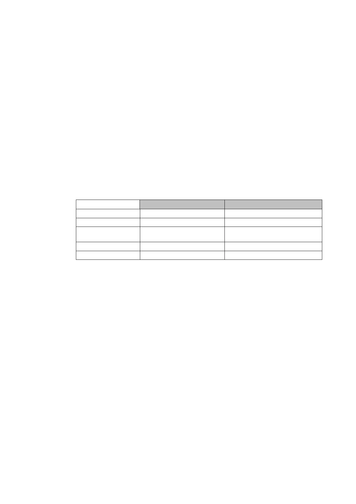
Typical time constant values are given in the following table.
Time constant 1
(mN)
Limits
Air-core reactors 40
Capacitor banks 10
Overhead lines 10
Cross section ≥ 100 mm
2
Cu or 150 mm
2
Al
Cables 60 – 90 Typical, at 66 kV and above
Busbars 60
Table 9: Typical protected plant thermal time constants
4.9.1.2 Dual time constant characteristic (Typically not applied for MiCOMho P443)
This characteristic is used to protect oil-filled transformers with natural air cooling (e.g. type
ONAN). The thermal model is similar to that with the single time constant, except that two
time constants must be set. The thermal curve is defined as:
0.4 exp(-t/τ1) + 0.6 exp(-t/τ2) = (Ι
2
– (k.Ι
FLC
)
2
) / (Ι
2
– Ι
P
2
)
Where:
τ1 = Heating and cooling time constant of the transformer windings;
τ2 = Heating and cooling time constant for the insulating oil.
For marginal overloading, heat will flow from the windings into the bulk of the insulating oil.
Therefore, at low current, the replica curve is dominated by the long time constant for the oil.
This provides protection against a general rise in oil temperature.
For severe overloading, heat accumulates in the transformer windings, with little opportunity
for dissipation into the surrounding insulating oil. Therefore, at high current, the replica curve
is dominated by the short time constant for the windings. This provides protection against hot
spots developing within the transformer windings.
Overall, the dual time constant characteristic provided within the relay serves to protect the
winding insulation from ageing, and to minimise gas production by overheated oil. Note,
however, that the thermal model does not compensate for the effects of ambient temperature
change.
The current setting is calculated wuth Thermal Trip = Permissible continuous loading of the
transformer / CT ratio.
Typical time constants:
 Loading...


