MiCOM P40 Agile P442, P444
(GS) 3-
Update settings?
Enter or clear
Pressing will result in the new settings being adopted, pressing will cause the relay to
discard the newly entered values. It should be noted that, the setting values will also be
discarded if the menu time out occurs before the setting changes have been confirmed.
Control and support settings will be updated immediately after they are entered, without
‘Update settings?’ prompt.
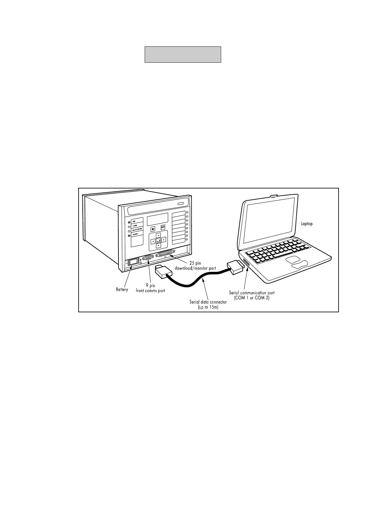
1.9 Front communication port user interface
The front communication port is provided by a 9-pin female D-type connector located under
the bottom hinged cover. It provides EIA(RS)232 serial data communication and is intended
for use with a PC locally to the relay (up to 15m distance) as shown in Figure 7. This port
supports the Courier communication protocol only. Courier is the communication language
developed by Alstom Grid to allow communication with its range of protection relays. The
front port is particularly designed for use with the relay settings program MiCOM S1 a
Windows 95/NT based software package.
Figure 7: Front port connection
The relay is a Data Communication Equipment (DCE) device. Therefore the pin connections
of the relay’s 9-pin front port are as follows:
Pin no. 2 Tx Transmit data
Pin no. 3 Rx Receive data
Pin no. 5 0V Zero volts common
None of the other pins are connected in the relay. The relay should be connected to the
serial port of a PC, usually called COM1 or COM2. PCs are normally Data Terminal
Equipment (DTE) devices that have a serial port pin connection as below (if in doubt check
your PC manual):
25 Way 9 Way
Pin no. 3 2 Rx Receive data
Pin no. 2 3 Tx Transmit data
Pin no. 7 5 0V Zero volts common
For successful data communication, the Tx pin on the relay must be connected to the Rx pin
on the PC, and the Rx pin on the relay must be connected to the Tx pin on the PC, as shown
in Figure 8. Therefore, providing that the PC is a DTE with pin connections as given above, a
‘straight through’ serial connector is required, i.e. one that connects pin 2 to pin 2, pin 3 to
pin 3, and pin 5 to pin 5. Note that a common cause of difficulty with serial data
 Loading...


