P44x/EN CM/Hb
MiCOM P40 Agile P442, P444
(CM) 9-
5.3.1.2 Default simulation principle
To simulate a single-phase fault
The distance protection detects a single-phase default in E if the impedance and phase of
this point place it inside the characteristic. The relation between the impedance and phase
and the injected voltage and current is as follows:
• Fault Impedance Z = Vphase/Iphase;
• Fault Phase ϕ = phase-shift(Vphase, Iphase) ;
• The Vphase voltage has to remain lower than the rated voltage value
Impedance test for zone 1:
I1 = 1A
ϕ1 = line angle = 76°
= Zfault = Zd (1 + k0) + Rfault
Rfault = R loop
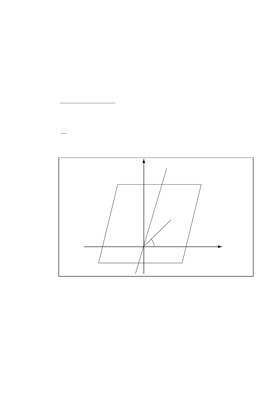
Distance X
Resistance R
Xlim
Rlim
E
j
Z
-Rlim
P3017ENa
Figure 7: Characteristic point determination (Rlim two-phase & Single-phase can be
different)
The characteristic angle is:
• For phase-to-phase: Argument of the positive impedance of the line (Z1)
• For phase-to-earth: Argument of 2Z1+Z0
The relay characteristic can be created and displayed with Z-Graph (MiCOM Z-Graph
software is a tool delivered with the protection)
 Loading...


