P44x/EN AP/Hb
MiCOM P40 Agile P442, P444
(AP) 5-
P0475ENa
R3PG-R4PG
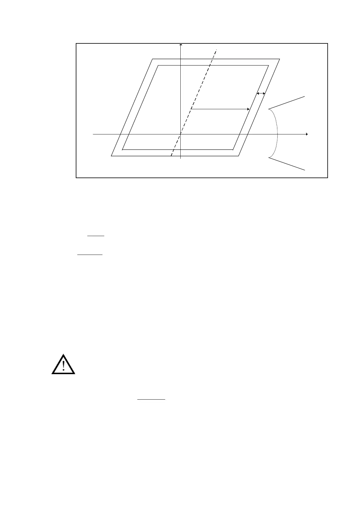
Zone 3
Zone 4
LOAD
RD
Z
Figure 20: Resistive reaches for load avoidance
As shown in the Figure, R3Ph-R4Ph is set such as to avoid point Z by a suitable margin.
Zone 3 must never reach more than 80% of the distance from the line characteristic
impedance (shown dotted), towards Z. However, where power swing blocking is used, a
larger impedance (including ∆R) characteristic surrounds zones 3 and 4, and it is essential
also that load does not encroach upon this characteristic. For this reason, R3Ph would be
set ≤ 60% of the distance from the line characteristic impedance towards Z. A setting
between the calculated minimum and maximum should be applied.
R/Z ratio: For best zone reach accuracy, the resistive reach of each zone would not normally
be set greater than 10 times the corresponding zone reach. This avoids relay overreach or
underreach where the protected line is exporting or importing power at the instant of fault
inception. The resistive reach of any other zone cannot be set greater than R3Ph, and where
zone 4 is used to provide reverse directional decisions for Blocking or Permissive Overreach
schemes, the zone 2 elements used in the scheme must satisfy R2Ph ≤ (R3Ph-R4Ph) x
80%.
3.1.2.4.2 Resistive reach calculation – Earth fault Element
The resistive reach setting of the relay earth fault elements (RG) should be set to cover the
desired level of earth fault resistance, but to avoid operation with minimum load impedance.
Fault resistance would comprise arc-resistance and tower footing resistance. In addition, for
best reach accuracy, the resistive reach of any zone of the relay would not normally be
greater than 10 times the corresponding earth loop reach.
EXPERT SECTION
As shown in Figure 20, R3G – R4G is set such as to avoid point Z (minimum load
impedance) by a suitable margin.
R3G – R4G ≤ 80% Z minimum load impedance
≤ 80%
Umin/√3;1
2 x Imax
• Vmin: minimum phase/phase voltage in normal conditions without fault
• Imax: maximum load current in normal conditions without fault
However, where Power swing blocking is used, a larger impedance surrounds zone 3 and
zone 4, and it is also essential for the load not to encroach upon the characteristic.
The earth detection criteria (10% IN + 5% IphaseMax) blocks the relay starting if residual
current is not detected (it secures the relay in case of load encroachment for Delta
algorithms).
When Phase-Phase detectors are used, phase ground start could be higher compared to
previous version, because ∆R is only applied to the phase-phase loops.
 Loading...


