P44x/EN ST/Hb
P442, P444 (ST) 4-
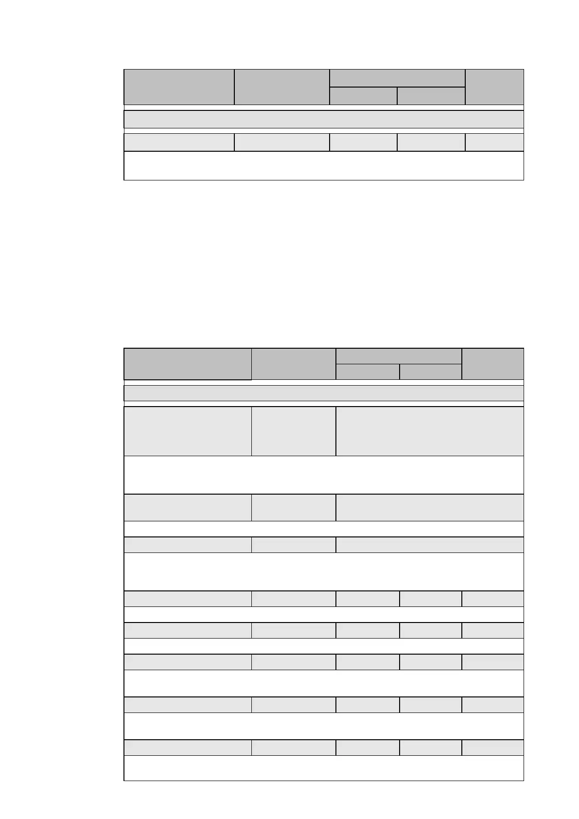
Menu text Default setting
Setting range
Step size
Min Max
GROUP 1: POWER SWING
Stable swing 1 1 255 1
Threshold of number of Stable Swings. Triggers DDB #353 when reached.
Setting of the number of steps to confirm Stable Swing condition.
2.4 Directional and non-directional overcurrent protection (“Back-up I>” menu)
The overcurrent protection included in the P442 and P444 relays provides two stage non-
directional / directional three-phase overcurrent protection and two non-directional stages
(I>3 and I>4), with independent time-delay characteristics. One or more stages may be
enabled to complement the relay distance protection. All overcurrent and directional settings
apply to all three-phases but are independent for each of the four stages. The first two
stages of overcurrent protection, I>1 and I>2 have time-delayed characteristics that are
selectable between inverse definite minimum time (IDMT), or definite time (DT).
All the stages trip three-phase only. They could be used for back up protection during a VT
failure.
The following table shows the relay menu for overcurrent protection, including the available
setting ranges and factory defaults.
Menu text Default setting
Step size
Min Max
GROUP 1 – BACK-UP I>
I>1 Function DT
Disabled, DT, IEC S Inverse, IEC V
Inverse, IEC E Inverse, UK LT Inverse,
IEEE M Inverse, IEEE V Inverse, IEEE E
Inverse, US Inverse, US ST Inverse
Sets the first phase overcurrent threshold (I>1) characteristics. The conditions are
‘disabled’, definite time (DT) or inverse definite minimum time (IDMT, see section
P44x/EN AP).
I>1 Direction Directional Fwd
Non-Directional, Directional Fwd,
Directional Rev
Sets the directional control for the first stage overcurrent element.
I>1 VTS Block Non-Directional Block, Non-Directional
When the directional control for the ‘I>1’ is set, sets the Voltage Transformer Supervision
(VTS) directionality (see section P44x/EN AP).
The operation of the VTS will block the stage
or will revert to Non-directional on operation of the VTS.
I>1 Current Set 1.50 x In 0.08 x In 10.00 x In 0.01 x In
Sets the value for the overcurrent threshold.
I>1 Time delay 1 s 0 s 100 s 0.01 s
Sets the time delay associated with I>1.
I>1 Time delay VTS 0.2 s 0 s 100 s 0.01 s
Sets the VTS time-delay. The VTS alarm will occur if VT fault occurs during more than the
VTS time-delay.
I>1 TMS 1 0.025 1.2 0.005
Sets the Time Multiplier Setting (TMS), to adjust the operating time of the IEC IDMT
characteristics.
I>1 Time Dial 7 0.5 15 0.1
Sets the time dial settings, to adjust the operating time of the IEEE/ US IDMT curves. The
Time Dial is a multiplier of the standard curve equation, to achieve the required tripping
 Loading...


