Design
P44x/EN FD/Hb
P444 (FD) 8-
2.5.2 Output relay board (standard)
The output relay board holds seven relays, three with normally open contacts and four with
changeover contacts. The relays are driven from the 22 V power supply line. The relays’
state is written to or read from using the parallel data bus. Depending on the relay model
seven additional output contacts may be provided, through the use of up to three extra relay
boards.
2.5.3 Output relay board (High speed / High break – Option)
The output relay board holds four relays, all normally open. The relays are driven from the
22 V power supply line. The relays’ state is written to or read from using the parallel data
bus.
A high speed output relay board contains a hybrid of MOSFET solid state devices (SSD) in
parallel with high capacity relay output contacts. The MOSFET has a varistor across it to
provide protection which is required when switching off inductive loads as the stored energy
in the inductor causes a reverse high voltage which could damage the MOSFET.
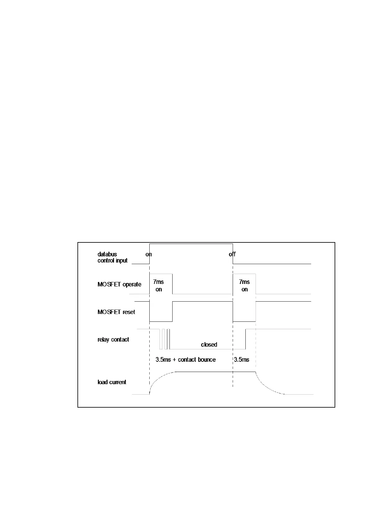
When there is a control input command to operate an output contact, the miniature relay is
operated at the same time as the SSD. The miniature relay contact closes in nominally
3.5 ms and is used to carry the continuous load current; the SSD operates in <0.2 ms and is
switched off after 7.5 ms. When the control input resets to open the contacts, the SSD is
again turned on for 7.5 ms. The miniature relay resets in nominally 3.5 ms before the SSD
and so the SSD is used to break the load. The SSD absorbs the energy when breaking
inductive loads and so limits the resulting voltage surge. This contact arrangement is for
switching dc circuits only. As the SSD comes on very fast (<0.2 ms) then these high break
output contacts have the added advantage of being very fast operating.
Figure 3: High break contact operation
2.6 IRIG-B board (P442 and P444 only)
The IRIG-B board is an order option which can be fitted to provide an accurate timing
reference for the relay. This is available as a modulated or de-modulated option depending
on the requirements. The IRIG-B signal is connected to the board via a BNC connector on
the back of the relay. The timing information is used to synchronise the relay’s internal real-
time clock to an accuracy of 1 ms. The internal clock is then used for the time tagging of the
event, fault maintenance and disturbance records.
 Loading...


