P44x/EN AP/Hb
MiCOM P40 Agile P442, P444
(AP) 5-
2.1.1 Phase-to-earth loop impedance
P3031ENa
V
A
V
B
V
C
Z
s
Z
s
i
C
i
A
Z
1
Z
s
i
B
Z
1
Z
1
V
CN
V
BN
V
AN
k
S
Z
S
k
0
Z
1
R
Fault
Location
of Distance Relay
R / Phase
X / Phase
Z
Fault
Z
1
R
Fault
/ (1+k
0
)
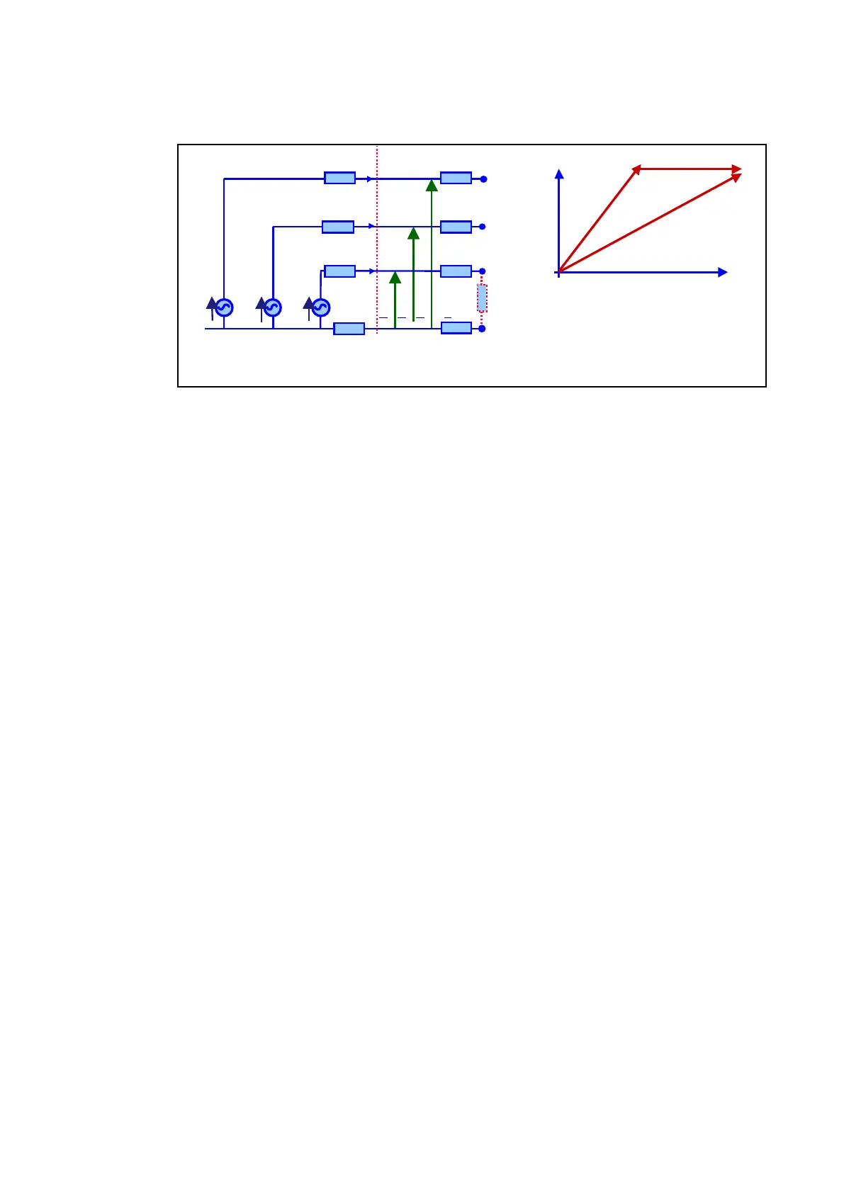
Figure 2: Phase-to-earth loop impedance
The impedance model for the phase-to-earth loop is:
VαN = Z1 x Dfault x (Iα + k
0
x 3I
0
) + Rfault x Ifault
with α = phase A, B or C
The (3I
0
) current is used for the first 40 ms to model the fault current, therefore eliminating
the load current before the circuit breakers are operated during the 40 ms (one pole tripping).
After the 40 ms, the phase current is used.
V
AN
= Z
1
.Dfault.(I
A
+k
0
x 3I
0
)+R
fault
.I
fault
V
BN
= Z
1
.Dfault.(I
B
+k
0
X
.3I
0
)+R
fault
.I
fault
V
CN
= Z
1
.Dfault.(I
C
+k
0
x 3I
0
)+R
fault
.I
fault
x 5 k
0
residual compensation factors
= 15 phase-to-earth loops are continuously monitored and computed for each samples.
 Loading...


