44x/EN AP/Hb6
-10 MiCOM P40 Agile
1.2.4 Additional Features for the P444 Relay Model
• Single pole tripping and autoreclose.
• Real Time Clock Synchronisation - Time synchronisation is possible from the relay
IRIG-B input. (IRIG-B must be specified as an option).
• Fibre optic converter for IEC 60870-5/103 communication (optional).
• Second rear port in COURIER Protocol (KBus/RS232/RS485)
• 24 Logic Inputs - For monitoring of the circuit breaker and other plant status.
• Up to 46 output relay contacts (with 12 high break relays)- For tripping, alarming,
status indication and remote control:
• Communication protocols available: K-Bus/Courier, MODBUS, VDEW (IEC 60870-5-
103), DNP3.0, IEC 61850 + Courier, IEC 61850 + IEC 60870-5-103) or DNP3.0 +
Courier.
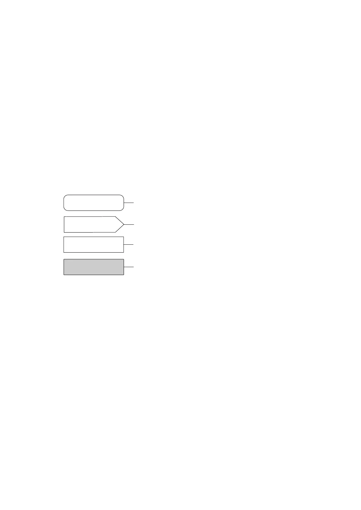
1.3 Explanation about specific symbols used in the logic diagrams
The following specific symbols are used in the logic diagrams. General symbols are shown in
section P44x/EN SG ‘Symbol and Glossary’:
Internal logic status from the logic of the protection (« the line
is dead » or « the pole is dead »)
User setting, adjustment or selection (IHM or MiCOM S1 Agile
)
Command / logical external status linked to an opto input from
the protection, or logical output.
Digital Data Bus (DDB) within the Programmable Scheme
Logic (PSL) corresponding to a command, a logical external
status or a logical output.
Check the DDB table for the reference number of each cell, included in P44x/EN PL.
 Loading...


