P44x/EN CM/Hb
MiCOM P40 Agile P442, P444
(CM) 9-
4.1.1 Visual Inspection
Carefully examine the relay to see that no physical damage has occurred since installation.
The rating information given under the top access cover on the front of the relay should be
checked to ensure it is correct for the particular installation.
Ensure the case earthing connections, bottom left-hand corner at the rear of the relay case,
are used to connect the relay to a local earth bar using an adequate conductor.
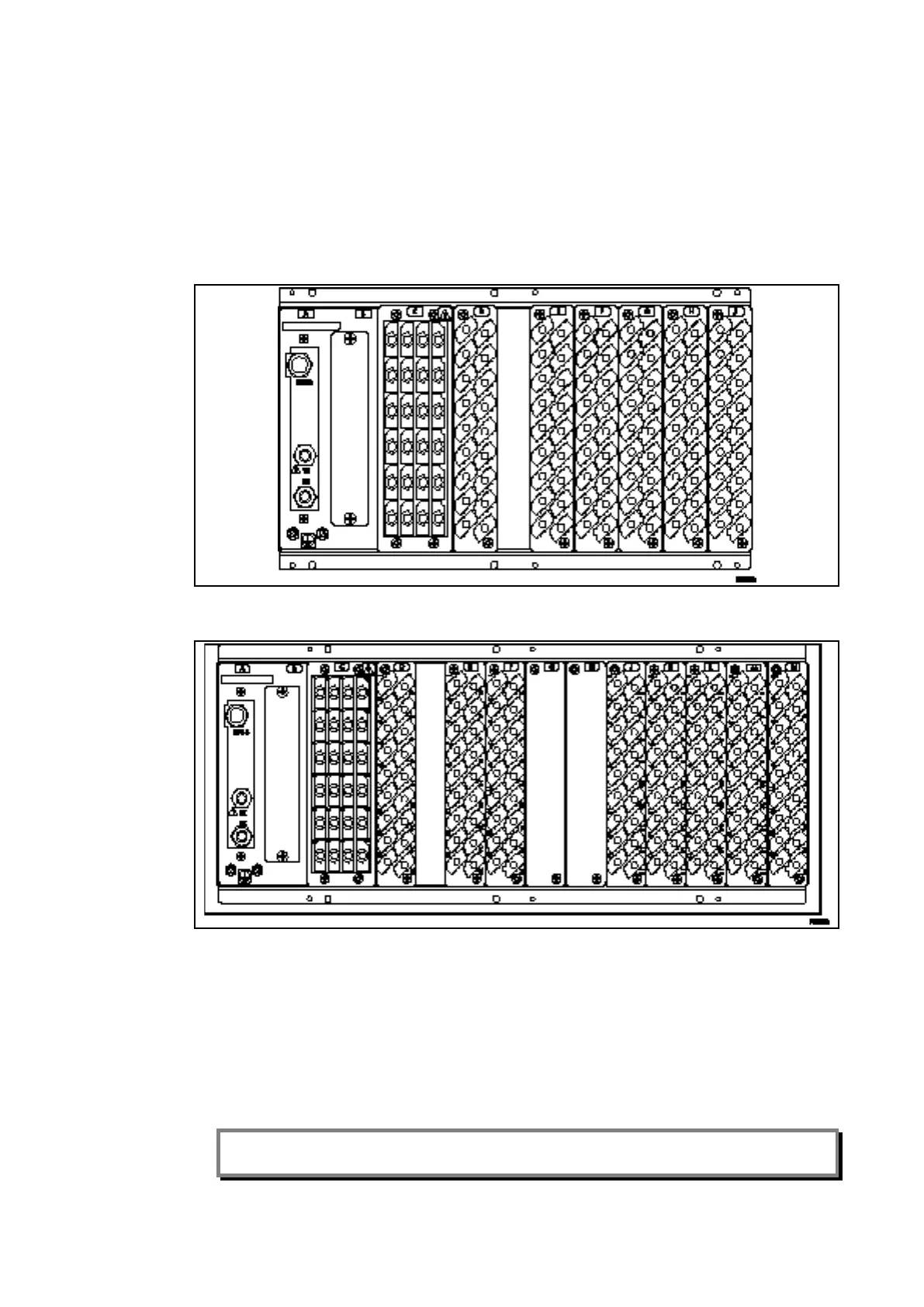
Figure 1a: Rear terminal blocks on size 60TE case (P442)
Figure 1b: Rear terminal blocks on size 80TE case (P444)
4.1.2 Current Transformer Shorting Contacts
If required, the current transformer shorting contacts can be checked to ensure they close
when the heavy duty terminal block is disconnected from the current input PCB.
The heavy duty terminal block is fastened to the rear panel using four crosshead screws.
These are located top and bottom between the first and second, and third and fourth,
columns of terminals.
Note: The use of a magnetic bladed screwdriver is recommended to minimize the risk of the
screws being left in the terminal block or lost.
Pull the terminal block away from the rear of the case and check that all the shorting
switches being used are closed with a continuity tester. Table 1 shows the terminals
between which shorting contacts are fitted.
 Loading...


