44x/EN AP/Hb6
-74 MiCOM P40 Agile
kZ0 Res. Comp, kZ0 = (Z
0
- Z
1
) / 3.Z
1
Ie: As a ratio.
kZ0 Angle, ∠kZ0 = ∠ (Z
0
- Z
1
) / 3.Z
1
Set in degrees.
Z
L0
- Z
L1
= (0.426 + j1.576) - (0.089 + j0.476)
= 0.337 + j1.1
= 1.15 / 72.9°
kZ0 =
1.15/ 72.9
3 0.484 / 79.4x
°
°
= 0.79 / –6.5°
Therefore, select:
kZ0 Res. Comp = 0.79 (Set for kZ1, kZ2, kZp, kZ4).
kZ0 Angle = –6.5° (Set for kZ1, kZ2, kZp, kZ4).
3.4.1.11 Resistive Reach Calculations
All distance elements must avoid the heaviest system loading. Taking the 5A CT secondary
rating as a guide to the maximum load current, the minimum load impedance presented to
the relay would be:
Vn
(phase-neutral)
/ In = (115 / √3) / 5 = 13.3 Ω (secondary)
Typically, phase fault distance zones would avoid the minimum load impedance by a margin
of ≥40% if possible (bearing in mind that the power swing characteristic surrounds the
tripping zones), earth fault zones would use a ≥20% margin. This allows maximum resistive
reaches of 7.9 Ω, and 10.6 Ω, respectively.
From Table 2: (see § 3.1.2.4), taking a required primary resistive coverage of 14.5Ω for
phase faults, and assuming a typical earth fault coverage of 40Ω, the minimum secondary
reaches become:
RPh (min) = 14.5 x 0.12 = 1.74 Ω (secondary);
RG (min) = 40 x 0.12 = 4.8 Ω (secondary).
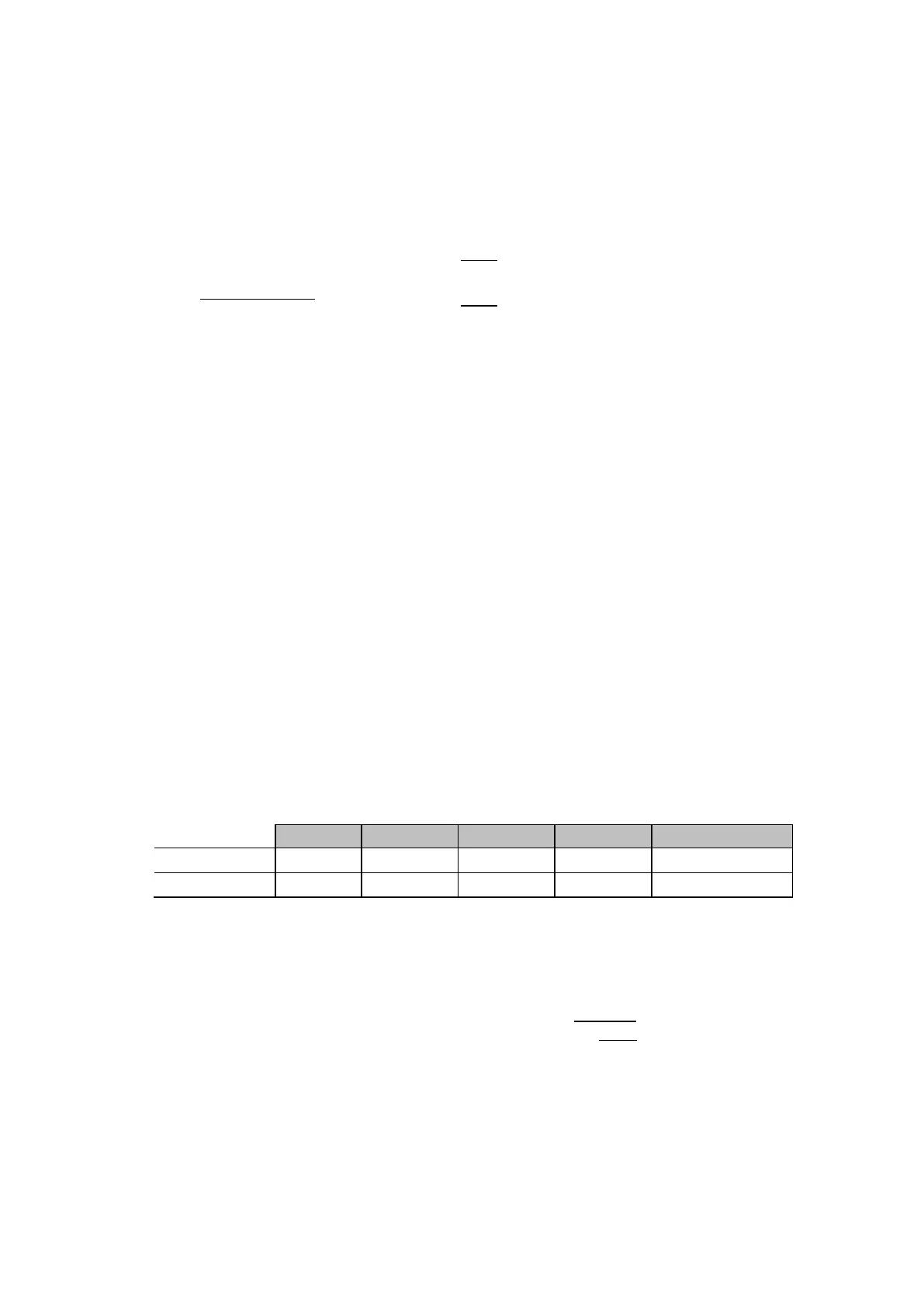
Resistive reaches could be chosen between the calculated values as shown in Table 10.
The zone 2 elements satisfy R2Ph ≤ (R3Ph x 80%), and R2G ≤ (R3G x 80%).
Minimum Maximum Zone 1 Zone 2 Zones 3 & 4
Phase (RPh) Ω
1.74 7.9 R1Ph = 3 R1Ph = 4 R3Ph-4Ph = 8
Earth (RG) Ω
4.8 10.6 R1G = 5 R1G = 6 R3G-4G = 10
Table 7: Selection of resistive reaches
R3Ph/2 = R4Ph/2 should be set ≤ 80% Z minimum load – ∆R.
3.4.1.12 Power Swing Band
Typically, the ∆R and ∆X band settings are both set between 10 - 30% of R3Ph. This gives a
secondary impedance between 0.6 and 1.8 Ω. For convenience, 1.0 Ω could be set.
The width of the power swing band is calculated as follows:
∆R = 1.3 × tan(π × ∆f × ∆t) × R
LOAD
Assuming that the load corresponds to 60° angles between sources and if the resistive reach
is set so that Rlim = R
LOAD
/2, the following is obtained:
∆R = 0.032 × ∆f × R
LOAD
To ensure that a power swing frequency of 5 Hz is detected, the following is obtained:
∆R = 0.16 × R
LOAD
 Loading...


