-8
MiCOM P40 Agile P442, P444
1.3 Relay connection and power-up
Before powering-up the relay, confirm that the relay power supply voltage and nominal ac
signal magnitudes are appropriate for your application. The relay serial number, and the
relay’s current and voltage rating, power rating information can be viewed under the top
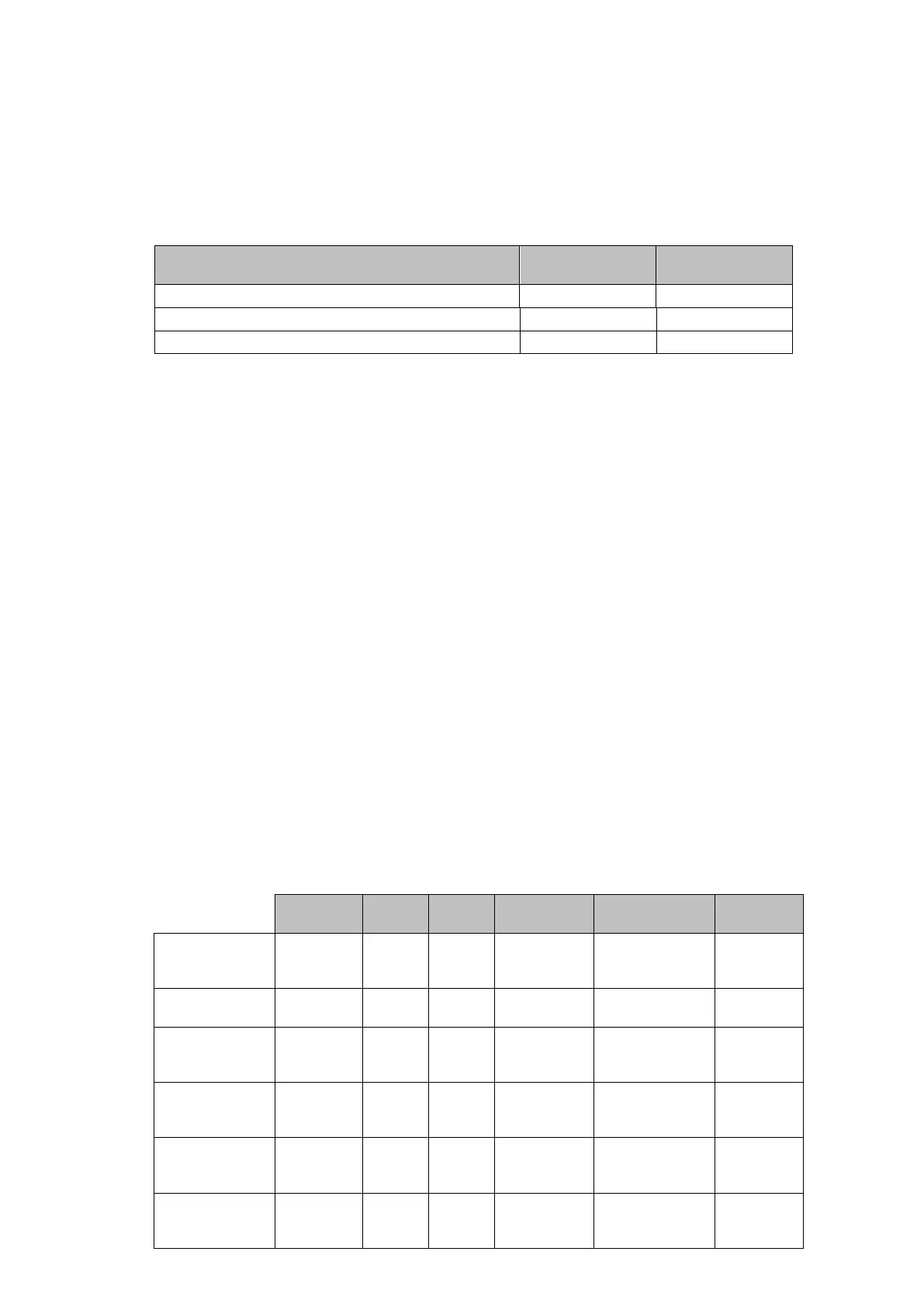
hinged cover. The relay is available in the following auxiliary voltage versions and these are
specified in the table below:
Nominal Ranges
Operative dc
Range
Operative ac
Range
24 – 48 V dc 19 to 65 V -
48 – 110 V dc (30 – 100 V ac rms) ** 37 to 150 V 24 to 110 V
110 – 250 V dc (100 – 240 V ac rms) ** 87 to 300 V 80 to 265 V
** rated for ac or dc operation
Please note that the label does not specify the logic input ratings. The P44x relays are fitted
with universal opto isolated logic inputs that can be programmed for the nominal battery
voltage of the circuit of which they are a part. See ‘Universal Opto input’ in the Firmware
section for more information on logic input specifications. Please note that the opto inputs
have a maximum input voltage rating of 300 V dc at any setting.
Once the ratings have been verified for the application, connect external power capable of
delivering the power requirements specified on the label to perform the relay familiarization
procedures. Figure 1 and 2 indicates the location of the power supply terminals but please
refer to the wiring diagrams in the Installation section for complete installation details
ensuring that the correct polarities are observed in the case of dc supply.
1.4 Introduction to the user interfaces and settings options
The relay has thre following interfaces:
• the front panel user interface via the LCD and keypad.
• the front port which supports Courier communication.
• the rear port which supports one protocol of either Courier, Modbus,
IEC 60870-5-103 or DNP3.0. The protocol for the rear port must be specified when t
he
r
elay is ordered.
• the optional Ethernet, dual Ethernet or 9-2 Ethernet port(s),
• The optional second rear port which supports Courier protocol.
The measurement information and relay settings which can be accessed from the three
interfaces are summarised in Table 1.
LCD
Courier Modbus IEC 870-5-103 DNP3.0 IEC 61850
(3)
Display &
modification of
all settings
• • • •
Digital I/O
signal status
Display/extracti
on of
measurements
• • • • • •
Display/extracti
on of fault
records
• • • • • •
Extraction of
disturbance
records
• • • • (Floc in %)
(1)
•
Programmable
scheme logic
settings
•
 Loading...


