44x/EN AP/Hb6
-34 MiCOM P40 Agile
3.1 Fault distance characteristics (“Distance elements” menu setting)
This section explains in detail the “Distance elements” menu setting. This menu is used to
set the line protection. The following sections contain line and zone setting application. A
general example of setting (distance elements and schemes) is presented in section 3.4.
Section 3.5 presents the logic of the distance protection (expert section).
The fault protection principle by zone is shown in the following diagram (basic distance fault
protection). Relay A and relay B cover the line protection by zone. In general, zones 1 and 2
provide main protection for the line or cable, with zone 3 (or zone 4) reaching further to
provide back up protection for faults on adjacent circuits.
P3052ENa
ZL
Z1A
A B
Z1B
Z1 Extension (A)
Z1 Extension (B)
Figure 13: Main protection principle
3.1.1 Line setting
All impedance reaches for phase fault protection are calculated in polar form: Z ∠θ, where Z
is the reach in ohms, and θ is the line angle setting in degrees, common to all zones.
The line parameters can be set in polar or rectangular form to give the total positive
impedance of the protected line:
3.1.2 Zone setting
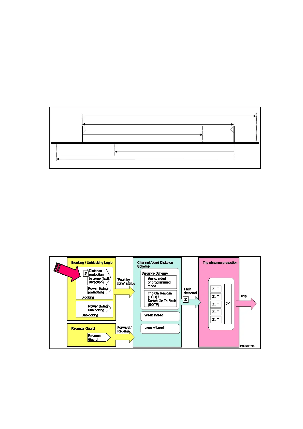
As shown in the following figure, the blocking / unblocking logic is based on a distance
protection by zone:
Figure 14: Fault detection by zone in the distance protection diagram
The Zone setting menu of the relay allows 6 zones setting.
 Loading...


