44x/EN MR/Hb6
Measurements and Recording
-8
1.2.3 Change of state of one or more output relay contacts.
If one or more of the output relay contacts has changed state since the last time that the
protection algorithm ran, then the new status is logged as an event. When this event is
selected to be viewed on the LCD, three applicable cells will become visible as shown below;
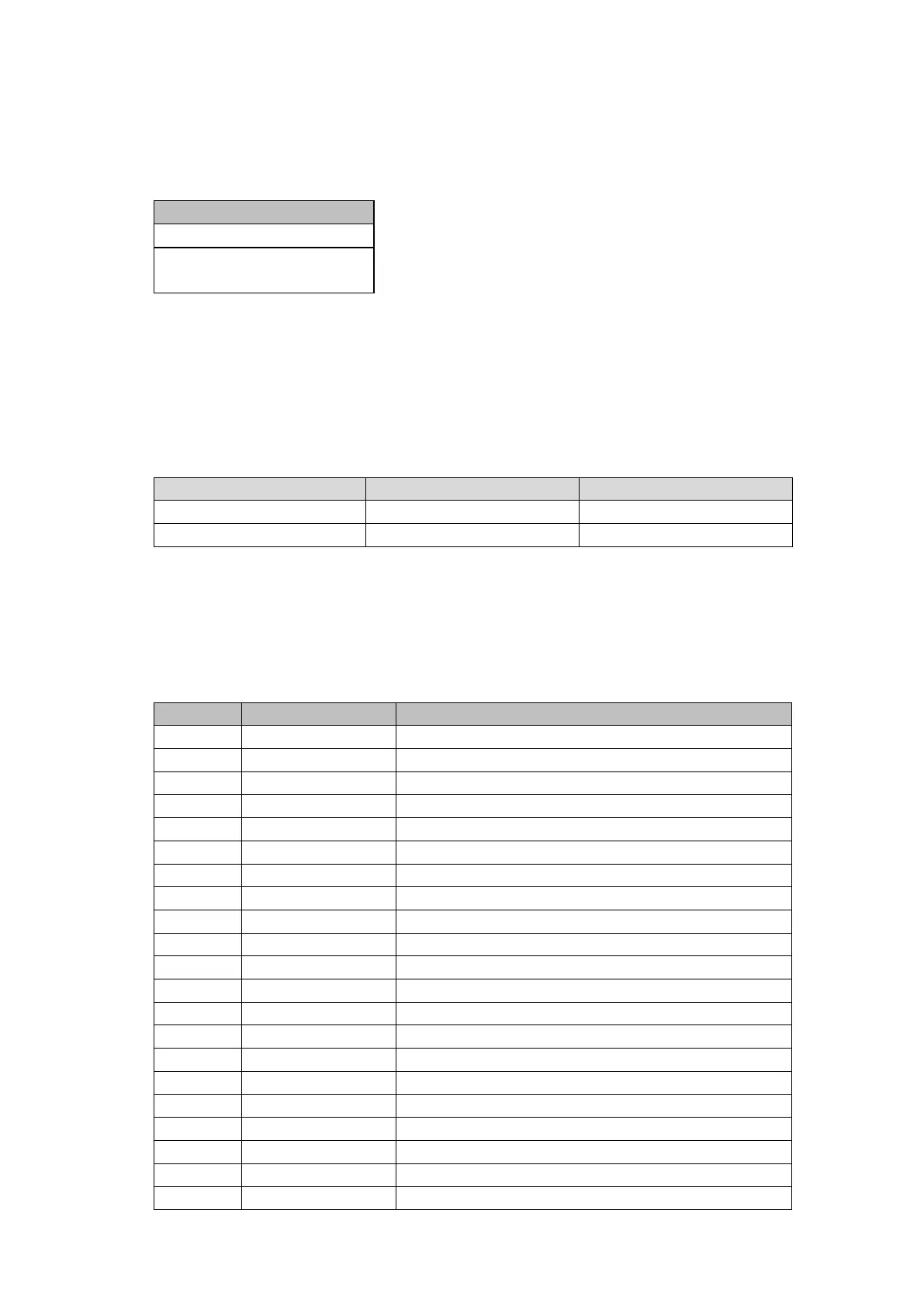
Contact Events
“OUTPUT CONTACTS”
“Event Value
010101010101010101010”
The Event Value is a 7, 14 or 21 bit word showing the status of the output contacts, where
the least significant bit (extreme right) corresponds to output contact 1 etc. The same
information is present if the event is extracted and viewed via PC.
1.2.4 Relay Alarm conditions.
Any alarm conditions generated by the relays will also be logged as individual events. The
following table shows examples of some of the alarm conditions and how they appear in the
event list:
Alarm Condition Event Text Event Value
Battery Fail Battery Fail ON/OFF Bit position 0 in 32 bit field
Field Voltage Fail Field Volt Fail ON/OFF Bit position 1 in 32 bit field
The previous table shows the abbreviated description that is given to the various alarm
conditions and also a corresponding value between 0 and 31. This value is appended to
each alarm event in a similar way as for the input and output events previously described. It
is used by the event extraction software, such as MiCOM S1 Agile, to identify the alarm and
is therefore invisible if the event is viewed on the LCD. Either ON or OFF is shown after the
description to signify whether the particular condition has become operated or has reset.
Alarm Event Text Explanation
Bit 0 Battery Fail Battery Fail
Bit 1 Field Volt Fail Field Voltage Fail
Bit 2 Prot'n Disabled Protection Disabled
Bit 3 F out of Range Frequency out of range
Bit 4 VT Fail Alarm VTS Alarm
Bit 5 CT Fail Alarm CTS Alarm
Bit 6 CB Fail Alarm CB Trip Fail Protection
Bit 7 I^ Maint Alarm Broken current Maintenance Alarm
Bit 8 I^ Lockout Alarm Broken current Lockout Alarm
Bit 9 CB Ops Maint No of CB Ops Maintenance Alarm
Bit 10 CB Ops Lockout No of CB Ops Lockout Alarm
Bit 11 CB Op Time Maint CB Op Time Maintenance Alarm
Bit 12 CB Op Time Lock CB Op Time Lockout Alarm
Bit 13 F.F. Pre Lockout Pre-alarm for lockout
Bit 14 F.F. Lock Excessive Fault Frequency Lockout Alarm
Bit 15 CB Status Alarm CB Status Alarm
Bit 16 Man CB Trip Fail CB Fail Trip Control
Bit 17 Man CB Cls Fail CB Fail Close Control
Bit 18 Man CB Unhealthy No Healthy Control Close
Bit 19 Control No C/S No C/S control close
Bit 20 A/R BAR Shot> A/R Lockout max shots
 Loading...


