P44x/EN AP/Hb
MiCOM P40 Agile P442, P444
(AP) 5-
Healthy Network = U
N
AND V
0
AND I
0
AND CVMR AND PSWING
5.8.1.5 INPUT / OUTPUT DDBs used in the PSL:
The following DDBs are associated to VTS in the PSL (see section P44x/EN PL)
Inputs:
• MCB/VTS Main
• MCB/VTS Synchro
Outputs:
• VTS Fast
• VT Fail Alarm
• Any Pole Dead
• All Pole Dead
5.8.2 Current Transformer Supervision (CTS)
The current transformer supervision feature is used to detect failure of one or more of the ac
phase current inputs to the relay. Failure of a phase CT or an open circuit of the
interconnecting wiring can result in incorrect operation of any current operated element.
Additionally, interruption in the ac current circuits risks dangerous CT secondary voltages
being generated.
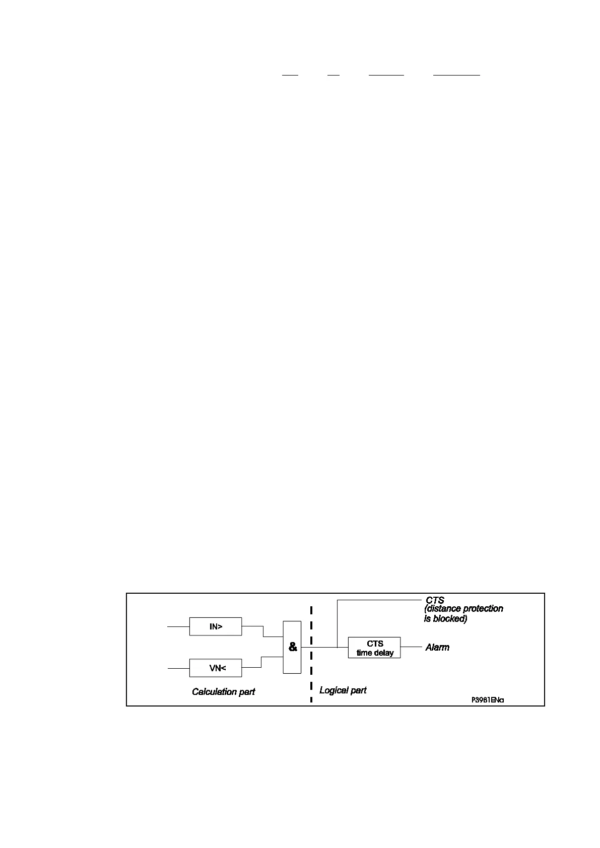
5.8.2.1 The CT Supervision Feature
The CT supervision feature operates on detection of derived (or measured) zero sequence
current, in the absence of corresponding derived (or measured) zero sequence voltage that
would normally accompany it. In this case, distance protection is blocked.
The voltage transformer connection used must be able to refer zero sequence voltages from
the primary to the secondary side. Therefore, this element should only be enabled where the
VT is of five limb construction, or comprises three single phase units, and has the primary
star point earthed.
Operation of the element will produce a time-delayed alarm visible on the LCD and event
record (DDB ‘CT Fail Alarm’ will be high), with an instantaneous block for inhibition of
protection elements. Protection elements operating from derived quantities (Broken
Conductor, Earth Fault, Neg Seq O/C) are always blocked on operation of the CT
supervision element.
5.8.2.2 Setting the CT Supervision Element
Figure 102: Basic CT supervision diagram
A “CTS fault” signal is sent out, after a settable time-delay if the conditions are as follows:
• The residual voltage is greater than the setting threshold during a delay greater
then time delay
• The residual current is greater than the setting threshold.
 Loading...


