44x/EN ST/Hb6
-66 MiCOM P40 Agile
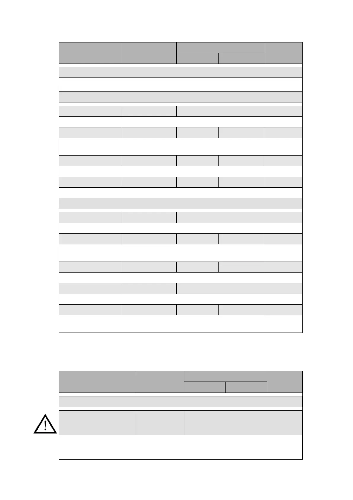
Menu Text Default Setting
Setting Range
Step Size
Min. Max.
SUPERVISION – GROUP 1
Sets the sensitivity of the superimposed current elements.
CT Supervision – Group 1
CTS Status Disabled Enabled / Disabled
Enables or disables the Circuit Transformer Supervision.
CTS VN< Inhibit 1 0.5 / 2V 22 / 88V 0.5 / 2 V
Sets the VN< inhibition threshold. The CTS alarm is inhibited if the residual voltage is
lower than this value.
CTS IN> Set 0.1 0.08 × In 4 × In 0.01 × In
Sets the residual current threshold.
CTS Time Delay 5 0s 10s 1s
Sets the time delay alarm.
CVT Supervision – Group 1
CVTS Status Disabled Enabled / Disabled
Enables or disables the capacitive voltage transformers supervision.
CVTS VN> 1V 0.5V 22V 0.5V
Sets the residual overvoltage threshold. A CVTS alarm is sent out if residual voltage is
greater than this value.
CVTS Time Delay 100s 0s 300s 0.01s
Sets the CVTS time delay alarm.
CVTS V2 Status Disabled Enabled / Disabled
This setting is to enable the citeria of the negative sequence voltage control.
CVTS V2> 1V 0.5V 22V 0.5V
Sets the negative sequence voltage threshold. A CVTS alarm is sent out providing CVTS
V2 Status is enabled and the negative sequence voltage is greater than this value.
3.16 Check synchronisation (“System check” menu)
The SYSTEM CHECKS menu contains all of the check synchronism settings for auto (“A/R”)
and manual (“Man”) reclosure and is shown in the table below along with the relevant default
settings:
Menu text Default setting
Setting range
Step size
Min Max
GROUP 1 – SYSTEM CHECK
C/S Check Scheme for A/R 111 Bit 0 (last bit): Live Bus / Dead Line,
Bit 1: Dead Bus / Live Line,
Bit 2 (first bit): Live Bus / Live Line.
Check synchronism scheme for Autoreclosure. At least, one condition must be selected to
activate the synchronism check logic. The Dead Bus / Dead Line can only be created using
PSL.
 Loading...


