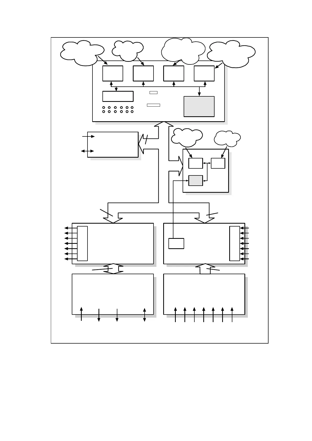
Main processor board
Relay board
Power supply board Transformer board
Input board
Parallel data bus
E²PROM
SRAM
Flash
EPROM
CPU
Front LCD panel
RS232 Front comms port
Parallel test port
LEDs
Current & voltage inputs (6 to 8)
Digital inputs (x8 or x16 or x24)
Power
supply
Rear RS485
communication port
Output relay contacts (x14 or x21 or x32)
ADC
IRIG-B board
optional
IRIG-B signal
Fibre optic
rear comms
port optional
Output relays
Opto-isolated
inputs
Analogue input signals
Power supply (3 voltages),
rear comms data
Digital input values
Power supply, rear comms
data, output relay status
Timing data
Watchdog
contacts
Field
voltage
Serial data bus
(sample data)
Alarm, event, fault,
disturbance &
maintenance record
Present values
of all
settings
Comms between
main & coprocessor
boards
CPU code & data,
setting
database data
CPU code & data
Default settings &
parameters, language text,
software code
Battery
backed-up
SRAM
CPU
FPGA SRAM
Coprocessor board
P3026ENb
 Loading...


