P44x/EN AP/Hb
MiCOM P40 Agile P442, P444
(AP) 5-
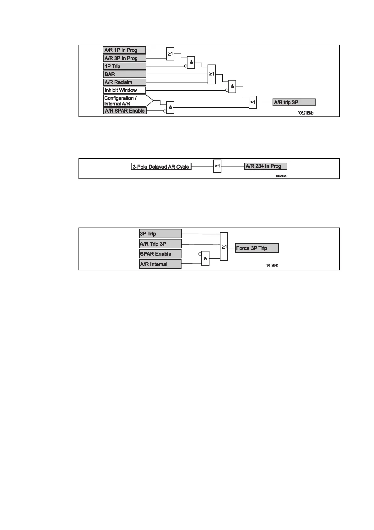
Figure 129: AR logic for 3p trip decision
Further autoreclose cycles (cycles 2, 3 and 4) in progress (AR 234 In Prog) logic:
Figure 130: Output dealayed autoreclose (for dead time 2, 3, 4)
If it is assigned to an opto input in the PSL and energised, The DDB: 'Force 3P Trip' signal
will force the internal single-phase protection to trip three-poles. (external order from Main1
to Main2 (P44x)) – the next trip will be three-pole.
Figure 131: Force 3P trip logic
5.11 Circuit breaker state monitoring
An operator at a remote location requires a reliable indication of the state of the switchgear.
Without an indication that each circuit breaker is either open or closed, the operator has
insufficient information to decide on switching operations. The relay incorporates circuit
breaker state monitoring, giving an indication of the position of the circuit breaker, or, if the
state is unknown, an alarm is raised.
The Circuit Breaker state can be locally displayed in the “System data / Plant status” menu.
5.11.1 Circuit Breaker State Monitoring Features
MiCOM relays can be set to monitor normally open (52a) and normally closed (52b) auxiliary
contacts of the circuit breaker. Under healthy conditions, these contacts will be in opposite
states. Should both sets of contacts be open, this would indicate one of the following
conditions:
• Auxiliary contacts / wiring defective
• Circuit Breaker (CB) is defective
• CB is in isolated position
Should both sets of contacts be closed, only one of the following two conditions would apply:
• Auxiliary contacts / wiring defective
• Circuit Breaker (CB) is defective
If any of the above conditions exist, an alarm will be issued after a 5s time delay. A normally
open / normally closed output contact can be assigned to this function via the programmable
scheme logic (PSL). The time delay is set to avoid unwanted operation during normal
switching duties.
In the PSL, CB AUX can be used or not, according to the four options below:
 Loading...


