P44x/EN AP/Hb
MiCOM P40 Agile P442, P444
(AP) 5-
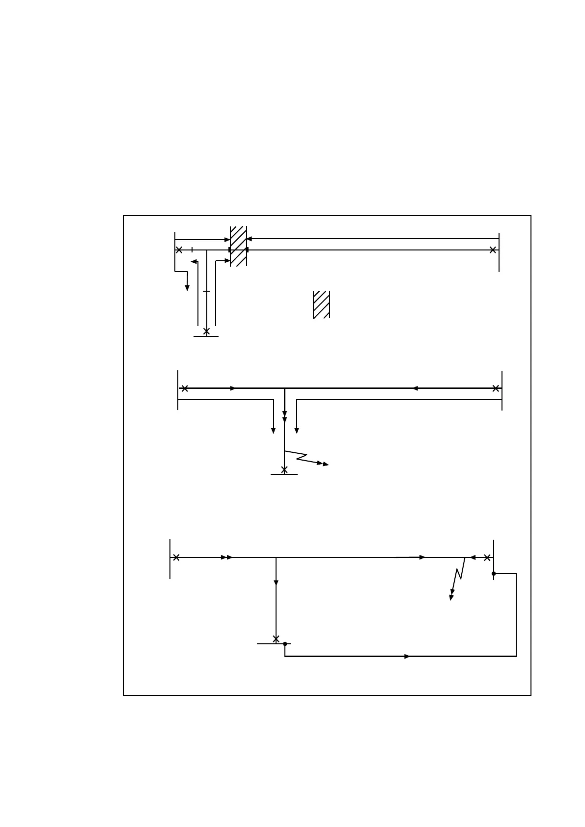
Figure 51 (i) shows the case where a short tee is connected close to another terminal. In this
case, zone 1 elements set to 80% of the shortest relative feeder length do not overlap. This
leaves a section not covered by any zone 1 element. Any fault in this section would result in
zone 2 time delayed tripping.
Figure 51 (ii) shows an example where terminal 'C' has no infeed. Faults close to this
terminal will not operate the relay at 'C' and hence the fault will be cleared by the zone 2
time-delayed elements of the relays at 'A' and 'B'.
Figure 51 (iii) illustrates a further difficulty for a PUP scheme. In this example current is
outfeed from terminal 'C' for an internal fault. The relay at 'C' will therefore see the fault as
reverse and not operate until the breaker at 'B' has opened; i.e. sequential tripping will occur.
A
Z1A
B
C
Z1C
= area where no zone 1 overlap exists
Fault
A
Z1A
B
C
Z1B
No infeed
Fault seen by A & B in zone 2
A
P3076EN
B
C
Relay at C sees reverse fault until B opens
(i)
(ii)
(iii)
Figure 51: Teed feeder applications
3.4.2.4 Blocking Schemes
Blocking schemes are particularly suited to the protection of teed feeders, since high speed
operation can be achieved where there is no current infeed from one or more terminals. The
scheme also has the advantage that only a common simplex channel or a triangulated
simplex channel is required.
 Loading...


