44x/EN AP/Hb6
-94 MiCOM P40 Agile
4.3 Directional and non-directional overcurrent protection
4.3.1 Inverse time characteristics
The inverse time-delay characteristics listed above comply with the following formula:
t = T ×
Where:
t = operation time
K = constant
I = measured current
Is = current threshold setting
α = constant
L = ANSI/IEEE constant (zero for IEC curves)
T = Time multiplier Setting
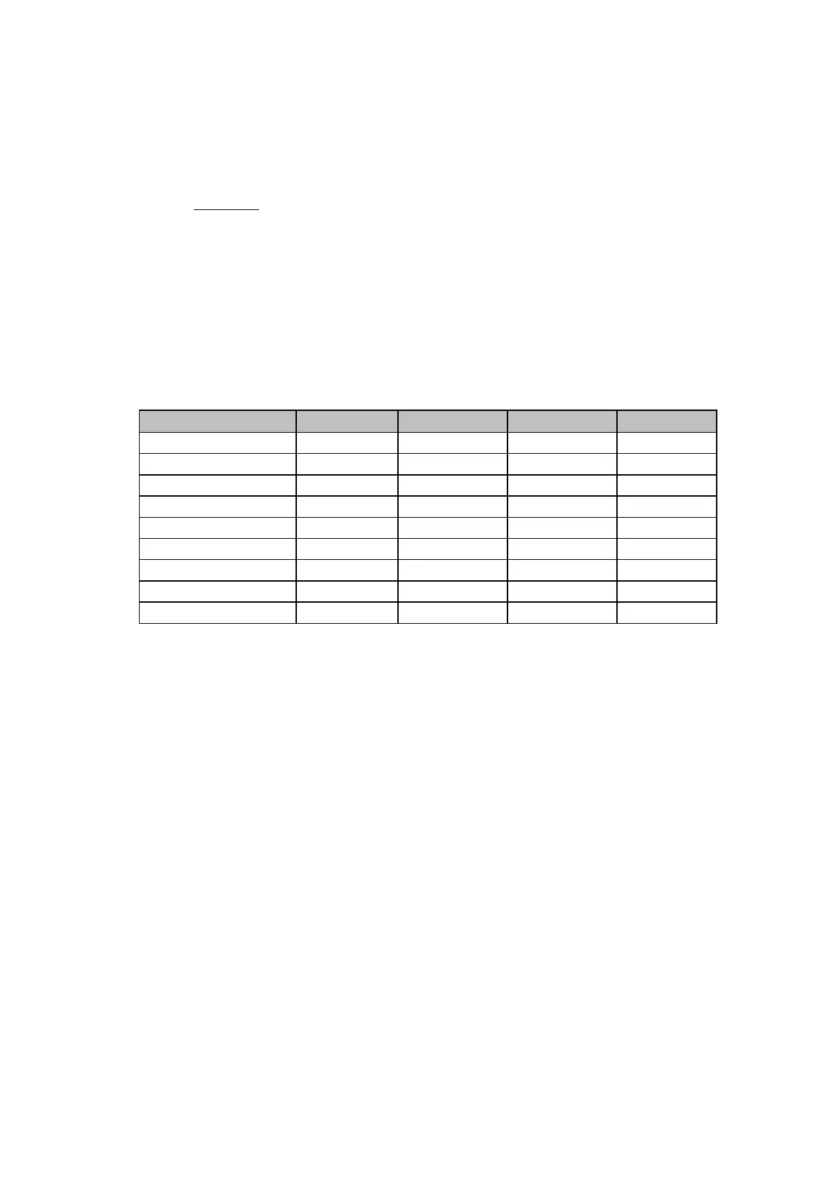
Curve description Standard K constant
constant
L constant
Standard Inverse IEC 0.14 0.02 0
Very Inverse IEC 13.5 1 0
Extremely Inverse IEC 80 2 0
Long Time Inverse UK 120 1 0
Moderately Inverse IEEE 0.0515 0.02 0.0114
Very Inverse IEEE 19.61 2 0.491
Extremely Inverse IEEE 28.2 2 0.1217
Inverse US 5.95 2 0.18
Short Time Inverse US 0.02394 0.02 0.1694
The IEEE and US curves are set differently to the IEC/UK curves, with regard to the time
setting. A time multiplier setting (TMS) is used to adjust the operating time of the IEC curves,
whereas a time dial setting is employed for the IEEE/US curves. Both the TMS and Time
Dial settings act as multipliers on the basic characteristics but the scaling of the time dial is
10 times that of the TMS, as shown in the previous menu. The menu is arranged such that if
an IEC/UK curve is selected, the I> Time Dial cell is not visible and vice versa for the TMS
setting.
4.3.2 Application of Timer Hold Facility
The first two stages of overcurrent protection in the P442 and P444 relays are provided with
a timer hold facility, which may either be set to zero or to a definite time value (Note that if an
IEEE/US operate curve is selected, the reset characteristic may be set to either definite or
inverse time in cell I>1 Reset Char; otherwise this setting cell is not visible in the menu).
Setting of the timer to zero means that the overcurrent timer for that stage will reset
instantaneously once the current falls below 95% of the current setting. Setting of the hold
timer to a value other than zero, delays the resetting of the protection element timers for this
period. This may be useful in certain applications, for example when grading with upstream
electromechanical overcurrent relays that have inherent reset time delays.
Another possible situation where the timer hold facility may be used to reduce fault clearance
times is where intermittent faults may be experienced. An example of this may occur in a
plastic insulated cable. In this application it is possible that the fault energy melts and reseals
the cable insulation, thereby extinguishing the fault. This process repeats to give a
succession of fault current pulses, each of increasing duration with reducing intervals
between the pulses, until the fault becomes permanent. When the reset time of the
overcurrent relay is instantaneous the relay may not trip until the fault becomes permanent.
By using the timer hold facility the relay will integrate the fault current pulses, thereby
reducing fault clearance time.
Note that the timer hold facility should not be used where high speed autoreclose with short
dead times are set.
 Loading...


