44x/EN AP/Hb6
-92 MiCOM P40 Agile
4.2 Load blinding (load avoidance)
Load blinders are provided for both phase and ground fault distance elements, to prevent
misoperation (mal-tripping) for heavy load flow. The purpose is to configure a blinder
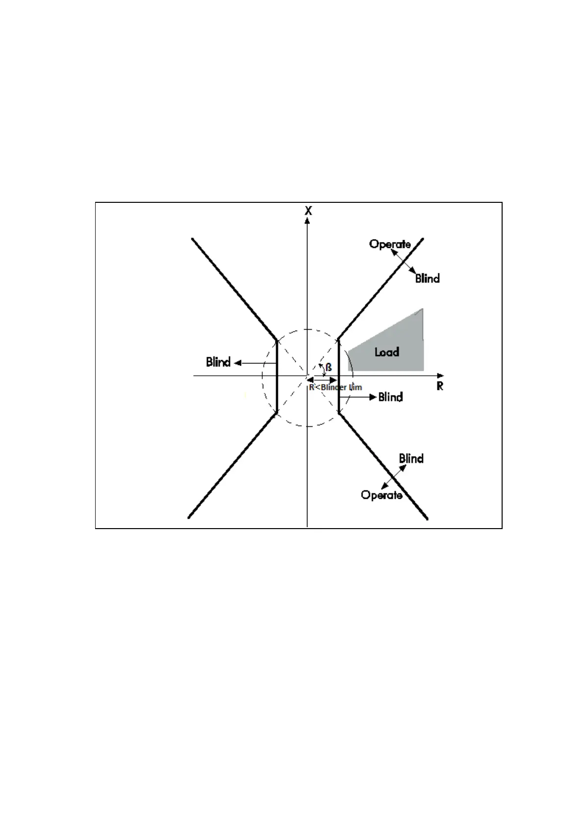
envelope which surrounds the expected worst case load limits, and to block tripping for any
impedance measured within the blinded region. Only a fault impedance which is outside of
the load area is allowed to cause a trip. The blinder characteristics are shown in
Figure 62: Load blinder characteristics
.
Figure 62: Load blinder characteristics
o R< Blinder Lim denotes the Load/B Resistance setting. This sets the cutoff of the
underimpedance .
o ß denotes the Load/B Angle setting. This sets the angle of the two blinder boundary
lines - the gradient of the rise or fall with respect to the resistive axis.
The P44x has a facility to allow the load blinder to be bypassed any time if:
• The measured voltage for the phase in question falls below an undervoltage V<
setting.
• A Delta Transition is confirmed. If load Blinder is enabled, an alternative Voltage Delta
threshold is used. A transition is confirmed by checking the values of V AND I. If
three consecutive samples for at least one loop are:
V > threshold VLB,
where threshold VLB = [ ((Un - Load Blinder V<) / Un) – 0.1 ] Un
V threshold VLB is limited to 10% to 50% of Un
and
I > threshold l, where threshold I = 0.2 In.
 Loading...


