P44x/EN IN/Hb
P442, P444 (IN) 14-
5 RELAY MOUNTING
MiCOM relays are dispatched either individually or as part of a panel/rack assembly.
Individual relays are normally supplied with an outline diagram showing the dimensions for
panel cut-outs and hole centres. This information can also be found in the product
publication.
Secondary front covers can also be supplied as an option item to prevent unauthorised
changing of settings and alarm status. They are available in sizes 40TE (GN0037 001) and
60TE (GN0038 001). Note that the 60TE cover also fits the 80TE case size of the relay.
The design of the relay is such that the fixing holes in the mounting flanges are only
accessible when the access covers are open and hidden from sight when the covers are
closed.
If a P991 or MMLG test block is to be included, it is recommended that, when viewed from
the front, it is positioned on the right-hand side of the relay (or relays) with which it is
associated. This minimises the wiring between the relay and test block, and allows the
correct test block to be easily identified during commissioning and maintenance tests.
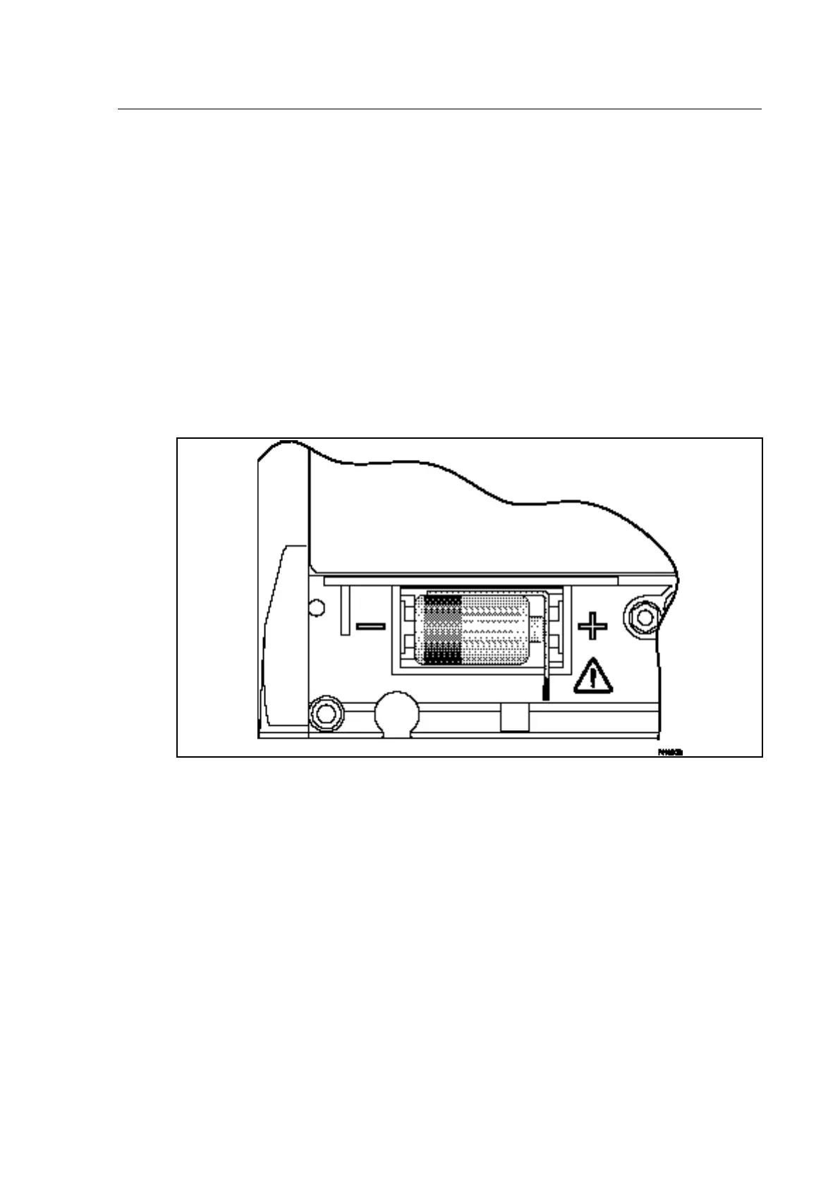
Figure 1 - Location of battery isolation strip
If it is necessary to test correct relay operation during the installation, the battery isolation
strip can be removed but should be replaced if commissioning of the scheme is not
imminent. This will prevent unnecessary battery drain during transportation to site and
installation. The red tab of the isolation strip can be seen protruding from the positive side of
the battery compartment when the lower access cover is open. To remove the isolation strip,
pull the red tab whilst lightly pressing the battery to prevent it falling out of the compartment.
When replacing the battery isolation strip, ensure that the strip is refitted as shown in Figure
1, ie. with the strip behind the battery with the red tab protruding.
 Loading...


