tenance
P44x/EN MT/Hb
P444 (MT) 10-
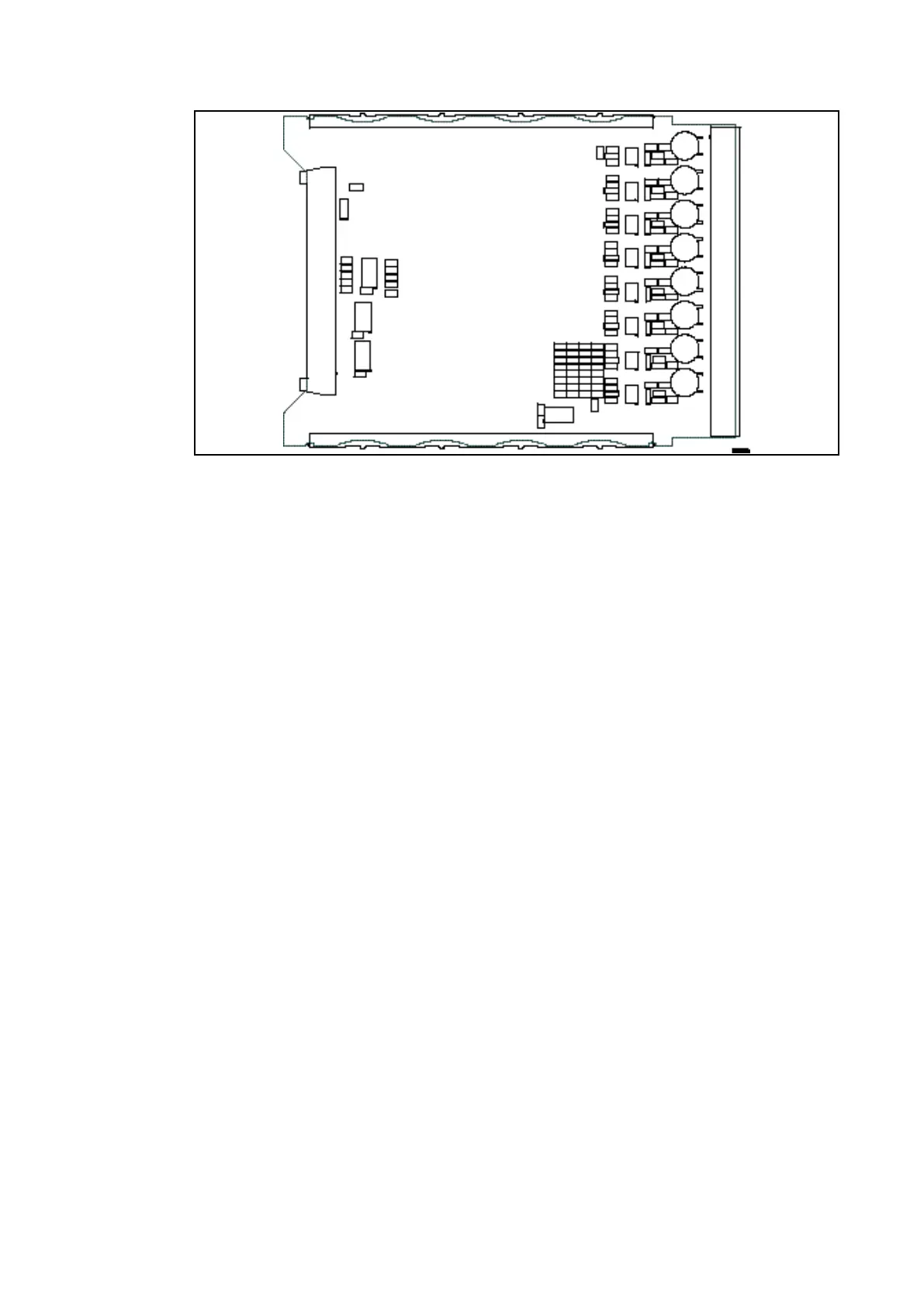
Figure 9 – Typical Opto Board
Once the relay has been reassembled after repair, it should be recommissioned in
accordance with the instructions in sections 1 to 7 (inclusive) of this document.
1.3.2.7 Replacement of the opto and separate relay boards
To remove either, gently pull the faulty PCB forward and out of the case.
If the relay board is being replaced, ensure the setting of the link (located above IDC
connector) on the replacement relay board is the same as the one being replaced. To help
identify that the correct board has been removed, Figure 10 shows the layout of the opto
board.
Before fitting the replacement PCB check that the number on the round label adjacent to the
front edge of the PCB matches the slot number into which it will be fitted. If the slot number
is missing or incorrect write the correct slot number on the label.
The replacement PCB should be carefully slid into the appropriate slot, ensuring that it is
pushed fully back on to the rear terminal blocks.
Refit the front panel using the reverse procedure to that given in section 1.3.2. After refitting
and closing the access covers on size 80TE cases, press at the location of the
hinge-assistance T-pieces so that they click back into the front panel moulding.
Once the relay has been reassembled after repair, it should be recommissioned in
accordance with the instructions in sections 1 to 8 inclusive (see commissioning and
maintenance section in P44x/EN CM).
 Loading...


