44x/EN AP/Hb6
-134 MiCOM P40 Agile
a valid message are quite small. In this case, it is recommended that the “IM# Fallback
Mode” is set to “Default” with a minimum “IM# FrameSyncTim” setting i.e. whenever a non-
valid message is received, InterMiCOM will use the set default value.
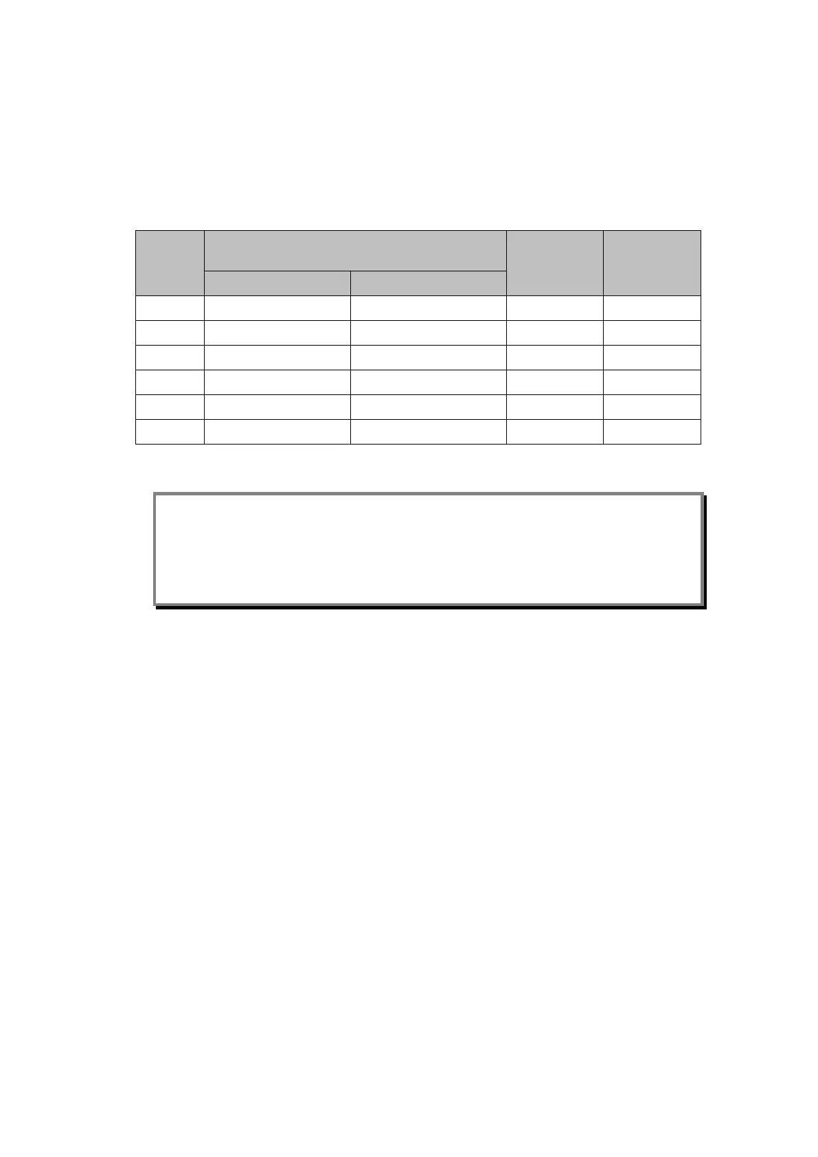
If “Permissive” mode is selected, the chances of receiving a valid message is between that
of the “Blocking” and “Direct Intertrip” modes. In this case, it is possible that the “IM#
Fallback Mode” is set to “Latched”. The table below highlights the recommended “IM#
FrameSyncTim” settings for the different signalling modes and baud rates:
Baud
Rate
Minimum Recommended “IM#
FrameSyncTim” Setting
Minimum
Setting
Maximum
Setting
Direct Intertrip Mode
Blocking Mode
600 100 250 100 1500
1200 50 130 50 1500
2400 30 70 30 1500
4800 20 40 20 1500
9600 10 20 10 1500
19200 10 10 10 1500
Table 12: Recommended frame synchronism time settings
Note: No recommended setting is given for the Permissive mode since it is anticipated that
“Latched” operation will be selected. However, if “Default mode” is selected, the “IM#
FrameSyncTim” setting should be set greater than the minimum settings listed above.
If the “IM# FrameSyncTim” setting is set lower than the minimum setting listed above,
there is a danger that the relay will monitor a correct change in message as a
corrupted message.
A setting of 25% is recommended for the communications failure alarm.
5.6.3.2 InterMiCOM Statistics & Diagnostics
It is possible to hide the channel diagnostics and statistics from view by setting the “Ch
Statistics” and/or “Ch Diagnostics” cells to “Invisible”. All channel statistics are reset when
the relay is powered up, or by user selection using the “Reset Statistics” cell.
5.6.4 Testing InterMiCOM Teleprotection
5.6.4.1 InterMiCOM Loopback Testing & Diagnostics
A number of features are included within the InterMiCOM function to assist a user in
commissioning and diagnosing any problems that may exist in the communications link.
“Loopback” test facilities, located within the INTERMICOM COMMS column of the relay
menu, provide a user with the ability to check the software and hardware of the InterMiCOM
signalling. By selecting “Loopback Mode” to “Internal”, only the internal software of the relay
is checked whereas “External” will check both the software and hardware used by
InterMiCOM. In the latter case, it is necessary to connect the transmit and receive pins
together (pins 2 and 3) and ensure that the DCD signal is held high (connect pin 1 and pin 4
together). When the relay is switched into “Loopback Mode” the relay will automatically use
generic addresses and will inhibit the InterMiCOM messages to the PSL by setting all eight
InterMiCOM message states to zero. The loopback mode will be indicated on the relay
frontplate by the amber Alarm LED being illuminated and a LCD alarm message, “IM
Loopback”.
 Loading...


