P44x/EN CM/Hb
MiCOM P40 Agile P442, P444
(CM) 9-
The alarm and out of service LEDs can be tested using the COMMISSIONING TESTS menu
column. Set cell [0F0E: COMMISSIONING TESTS, Test Mode] to ‘Enabled’. Check that the
alarm and out of service LEDs illuminate.
It is not necessary to return cell [0F0E: COMMISSIONING TESTS, Test Mode] to ‘Disabled’
at this stage because the test mode will be required for later tests.
Testing the trip LED
The trip LED can be tested by initiating a manual circuit breaker trip from the relay.
However, the trip LED will operate during the setting checks performed later. Therefore no
further testing of the trip LED is required at this stage.
Testing the user-programmable LEDs
To test the user-programmable LEDs set cell [0F12: COMMISSIONING TESTS, Test LEDs]
to ‘Apply Test’. Check that all 8 LEDs on the right-hand side of the relay illuminate.
4.2.6 Field Voltage Supply
The relay generates a field voltage of nominally 48 V that should be used to energise the
opto-isolated inputs.
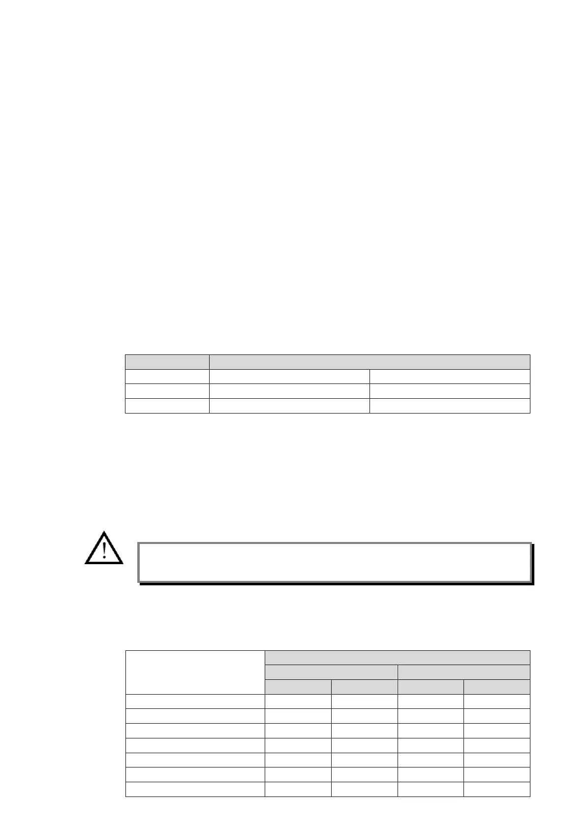
Measure the field voltage across the terminals given in Table 4. Check that the field voltage
is present at each positive and negative terminal and that the polarity is correct.
Repeat for terminals 8 and 10.
P442 P444
+48 Vdc J7 & J8 N7 & N8
–48 Vdc J9 & J10 N9 & N10
Table 4 - Field Voltage Terminals
4.2.7 Input Opto-isolators
This test checks that all the opto-isolated inputs are functioning correctly. P442 relays have
16 opto-isolated inputs and P444 relays have 24 opto-isolated inputs.
The opto-isolated inputs should be energised one at a time. Ensuring correct polarity,
connect the field supply voltage to the appropriate terminals for the input being tested. The
opto-isolated input terminal allocations are given in Table 5.
Note: The opto-isolated inputs may be energised from an external 50 V battery in some
installations. Check that this is not the case before connecting the field voltage
otherwise damage to the relay may result.
The status of each opto-isolated input can be viewed using cell [0020: SYSTEM DATA,
Opto I/P Status], a ‘1’ indicating an energised input and a ‘0’ indicating a de-energised input.
When each opto-isolated input is energised one of the characters on the bottom line of the
display will change to the value shown in Table 5 to indicate the new state of the inputs.
Apply field voltage to terminals
P442 P444
Opto input 1 D1 D2 D1 D2
Opto input 2 D3 D4 D3 D4
Opto input 3 D5 D6 D5 D6
Opto input 4 D7 D8 D7 D8
Opto input 5 D9 D10 D9 D10
Opto input 6 D11 D12 D11 D12
Opto input 7 D13 D14 D13 D14
 Loading...


