P44x/EN ST/Hb
P442, P444 (ST) 4-
improves sensitivity for earth faults. However, certain faults may arise which can remain
undetected by such schemes.
Any unbalanced fault condition will produce negative sequence current of some magnitude.
Therefore, a negative phase sequence overcurrent element can operate for both phase-to-
phase and phase to earth faults.
The following section describes how negative phase sequence overcurrent protection may
be applied in conjunction with standard overcurrent and earth fault protection to alleviate
some less common application difficulties.
• Negative phase sequence overcurrent elements give greater sensitivity to resistive
phase-to-phase faults, where phase overcurrent elements may not operate.
• In certain applications, residual current may not be detected by an earth fault relay
due to the system configuration. For example, an earth fault relay applied on the delta
side of a delta-star transformer is unable to detect earth faults on the star side.
However, negative sequence current will be present on both sides of the transformer
for any fault condition, irrespective of the transformer configuration. Therefore, a
negative phase sequence overcurrent element can be employed to provide time-
delayed back-up protection for any uncleared asymmetrical faults downstream.
• Where rotating machines are protected by fuses, loss of a fuse produces a large
amount of negative sequence current. This is a dangerous condition for the machine
due to the heating effects of negative phase sequence current and so an upstream
negative phase sequence overcurrent element may be applied to provide back-up
protection for dedicated motor protection relays.
• It may be required to simply alarm for the presence of negative phase sequence
currents on the system. Operators may then investigate the cause of the unbalance.
The negative phase sequence overcurrent element has a current pick up setting ‘I2> Current
Set’, and is time delayed in operation by the adjustable timer ‘I2> Time Delay’. The user may
choose to directionalise operation of the element, for either forward or reverse fault
protection for which a suitable relay characteristic angle may be set. Alternatively, the
element may be set as non-directional.
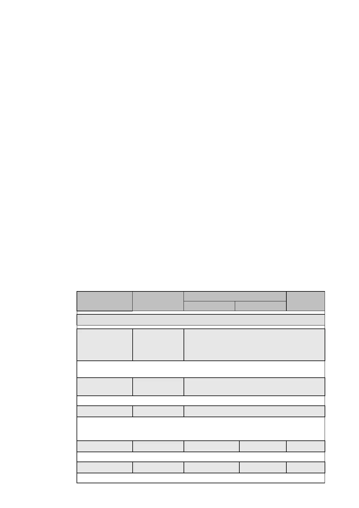
The relay menu for the negative sequence overcurrent element is shown below:
Menu text Default setting
Step size
Min Max
GROUP 1 – NEG SEQUENCE O/C
I2>1 Function DT Disabled, DT, IEC S Inverse, IEC V Inverse, IEC
E Inverse, UK LT Inverse, IEEE M Inverse, IEEE
V Inverse, IEEE E Inverse, US Inverse, US ST
Inverse
Sets the first negative sequence overcurrent (I2>1) characteristics. The conditions are
‘disabled’, definite time (DT) or inverse definite minimum time (IDMT).
I2>1 Directional Non-directional Non-directional, Directional FWD, Directional
REV
Sets the directional control for the fault.
I2>1 VTS Block Block Block, Non-directional
When the directional control for the ‘I2>1’ is set, sets the Voltage Transformer Supervision
(VTS) directionality. The operation of the VTS will block the stage or will revert to Non-
directional on operation of the VTS.
I2>1 Current Set 0.20 x In 0.08 x In 4.00 x In 0.01 x In
Sets the value for the negative sequence current threshold.
I2>1 Time Delay 10.00 s 0 s 100.0 s 0.01 s
Sets the time delay associated with I2>1.
 Loading...


