P44x/EN ST/Hb
P442, P444 (ST) 4-
• Communication with the relay can be started (Device \ open connection \ address1 \
pword AAAA) and the PSL activated in the internal logic of the relay can be extracted,
displayed, modified and uploaded again to the relay.
• Any group from 1 to 4 can be modified (ref of group must be validated before
resenting the file from PC to relay)
Before creating a dedicated PSL for covering customised applications, please see the DDB
description cell by cell (set & reset conditions) in the table at the end of the technical guide
(Courier Database).
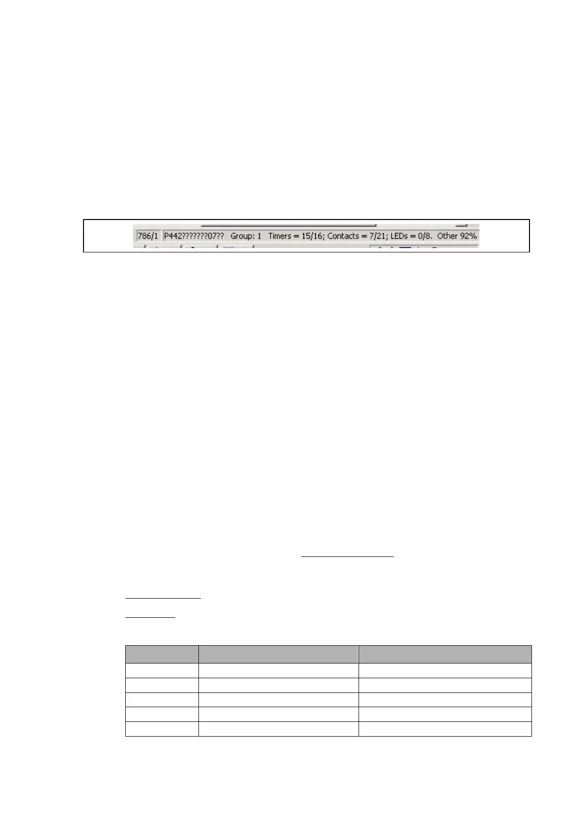
The type of model used by the relay in the settings or in the PSL is displayed at the bottom
of the screen in the status bar:
It indicates:
• Model number used (last 2 digits:???07??)
• PSL activated for Group1 logic
• Number of timers still available (15 out of a total of 16)
• Number of contacts still available (7 out of a total of 21 for P442 model)
• Number of LEDs still available (0 to 8 if all already assigned in the PSL)
• Memory capacity still available (decreases with the numbers of cells and logic gates
linked in the dedicated PSL)
(See also the section Commissioning document for further information on the tools)
4.2 Logic input mapping
The default mapping for each of the opto-isolated inputs are as shown in the following table:
• Version A: Opto inputs are in 48 VDC polarised (can be energised with the internal
field voltage offered by the relay
• Version B: Opto inputs are universal and opto input range can be selected in MiCOM
S1 Agile by:
Opto A – 48 VDC:
The opto inputs are specified to operate between 30 and 60 V to ensure there is enough
current flowing through the optocoupler diode to guarantee operation with component
tolerances, temperature and CTR (Current Transfer Ratio) downgrading over time.
Between 13-29 V lies the uncertainty band.
Below 12 V, the guaranteed logic state is Off
Opto B – Universal opto inputs:
Setting Guaranteed No Operation Guaranteed Operation
24/27 <16,2 >19,2
30/34 <20,4 >24,0
48/54 <32,4 >38,4
110/125 <75,0 >88,0
220/250 <150 >176,0
These margins ensure that ground faults on substation batteries do not cause maloperation
of the opto inputs.
 Loading...


