44x/EN MT/Hb6
-16 MiCOM P40 Agile P442,
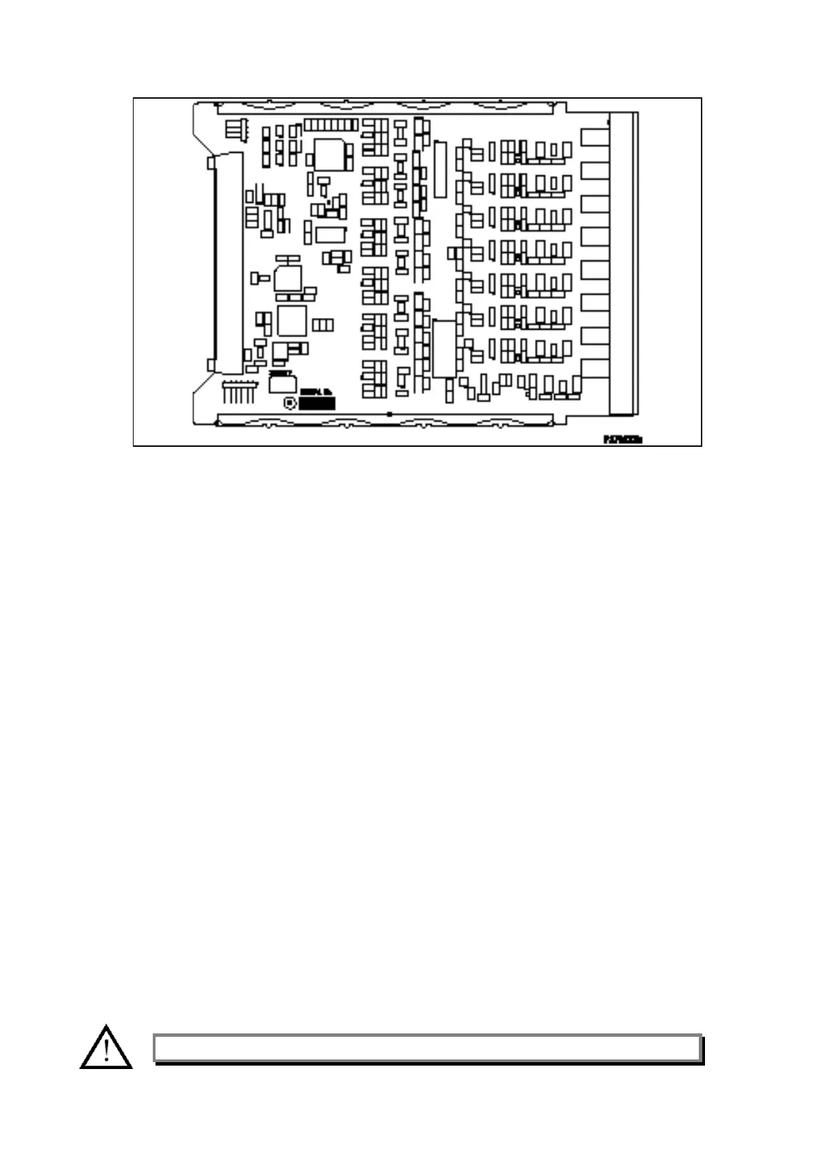
Figure 10: Typical opto board
1.4 Recalibration
Recalibration is not usually required when a PCB is replaced unless it happens to be one of
the two boards in the input module, the replacement of which directly affect the calibration.
Although it is possible to carry out an on-site recalibration, this requires test equipment with
suitable accuracy and a special calibration program to run on a PC. It is therefore
recommended that the work be carried out by the manufacturer, or entrusted to an approved
service centre.
1.5 Changing the battery
Each relay has a battery to maintain status data and the correct time when the auxiliary
supply voltage fails. The data maintained includes event, fault and disturbance records and
the thermal state at the time of failure.
This battery will periodically need changing, although an alarm will be given as part of the
relay’s continuous self-monitoring in the event of a low battery condition.
If the battery-backed facilities are not required to be maintained during an interruption of the
auxiliary supply, the steps below can be followed to remove the battery, but do not replace
with a new battery.
1.5.1 Instructions for Replacing The Battery
Open the bottom access cover on the front of the relay.
Gently extract the battery from its socket. If necessary, use a small screwdriver to prise the
battery free.
Ensure that the metal terminals in the battery socket are free from corrosion, grease and
dust.
The replacement battery should be removed from its packaging and placed into the battery
holder, taking care to ensure that the polarity markings on the battery agree with those
adjacent to the socket.
Note: Only use a type ½AA Lithium battery with a nominal voltage of 3.6 V.
 Loading...


