Lenze · i700 servo inverter · reference manual · DMS 3.0 EN · 06/2016 · TD06 106
5 Motor control & motor settings
5.10 Synchronous motor (SM): Pole position identification
_ _ _ _ _ _ _ _ _ _ _ _ _ _ _ _ _ _ _ _ _ _ _ _ _ _ _ _ _ _ _ _ _ _ _ _ _ _ _ _ _ _ _ _ _ _ _ _ _ _ _ _ _ _ _ _ _ _ _ _ _ _ _ _
5.10.2.1 Adapt pole position identification PPI (360°)
For drives with a high static friction, mass inertia or alternating load, an optimisation may be
required:
• The amplitude of the current vector has to be set so high that the motor can be accelerated with
a high mass inertia.
• The cyclic continued rotation of the current vector by 22.5° has to cause an equivalent angular
rotation of the motor shaft (rotor). A step function has to be achieved as displayed in the figure
[5-2]
. Here, actual positions with very low overshoots are visible.
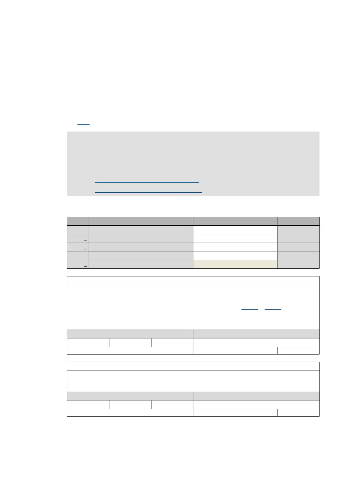
0x2C61 | 0x3461 - Pole position identification PPI (360°)
Stop!
If there is no temperature monitoring in the motor and/or the I²xt motor monitoring and
the maximum current monitoring are not parameterised correctly, the motor might be
damaged permanently when the current amplitude is set too high!
Monitoring of the motor utilisation (I²xt)
( 254)
Monitoring of the ultimate motor current
( 271)
Sub. Name Lenze setting Data type
1 PPI (360°): Current amplitude 100 % UNSIGNED_16
2 PPI (360°): Ramp time 40 s UNSIGNED_16
3 PPI (360°): Direction of rotation 0: Field: CW UNSIGNED_8
4 PPI (360°): Error tolerance 20 ° UNSIGNED_8
5 PPI (360°): Absolute current amplitude UNSIGNED_32
Subindex 1: PPI (360°): Current amplitude
Adjustment of the current amplitude in percent
• For large machines and high mass inertia values or for linear direct drives, the current amplitude usually has to
be increased.
• A Lenze setting of "100 %" corresponds to 141 % of the rated motor current (0x6075
or 0x6875 for axis B).
Note!
If the current amplitude is set to > 100 %, the device utilisation (Ixt) monitoring and/or one of the motor monitoring
functions may respond and cause the abort of the pole position identification.
Setting range (min. value | unit | max. value) Lenze setting
1 % 1000 100 %
Write access CINH OSC P RX TX UNSIGNED_16
Subindex 2: PPI (360°): Ramp time
Adjustment of the ramp time in percent
• For large machines and high mass inertia values, the ramp time usually has to be increased.
• For small machines, a reduction of the ramp time can speed up the pole position identification process.
Setting range (min. value | unit | max. value) Lenze setting
1 s 600 40 s
Write access CINH OSC P RX TX UNSIGNED_16

 Loading...


