7 CiA402 device profile
7.11 Touch probe (TP)
243
Lenze · i700 servo inverter · reference manual · DMS 3.0 EN · 06/2016 · TD06
_ _ _ _ _ _ _ _ _ _ _ _ _ _ _ _ _ _ _ _ _ _ _ _ _ _ _ _ _ _ _ _ _ _ _ _ _ _ _ _ _ _ _ _ _ _ _ _ _ _ _ _ _ _ _ _ _ _ _ _ _ _ _ _
7.11.2 General functional principle
If an event occurs at the touch probe source configured, a time stamp is recorded in the i700 servo
inverter.
The time stamp recorded is related to the system time and can thus be separated into two parts:
One part is the control cycle within which the event has occurred. The other part is the time
difference between the start of the control cycle determined and the actual detection of the event.
A history buffer enables the i700 servo inverter to know the last n position values. Thus, the actual
position at the start and end of the control cycle within which the event has occurred is known.
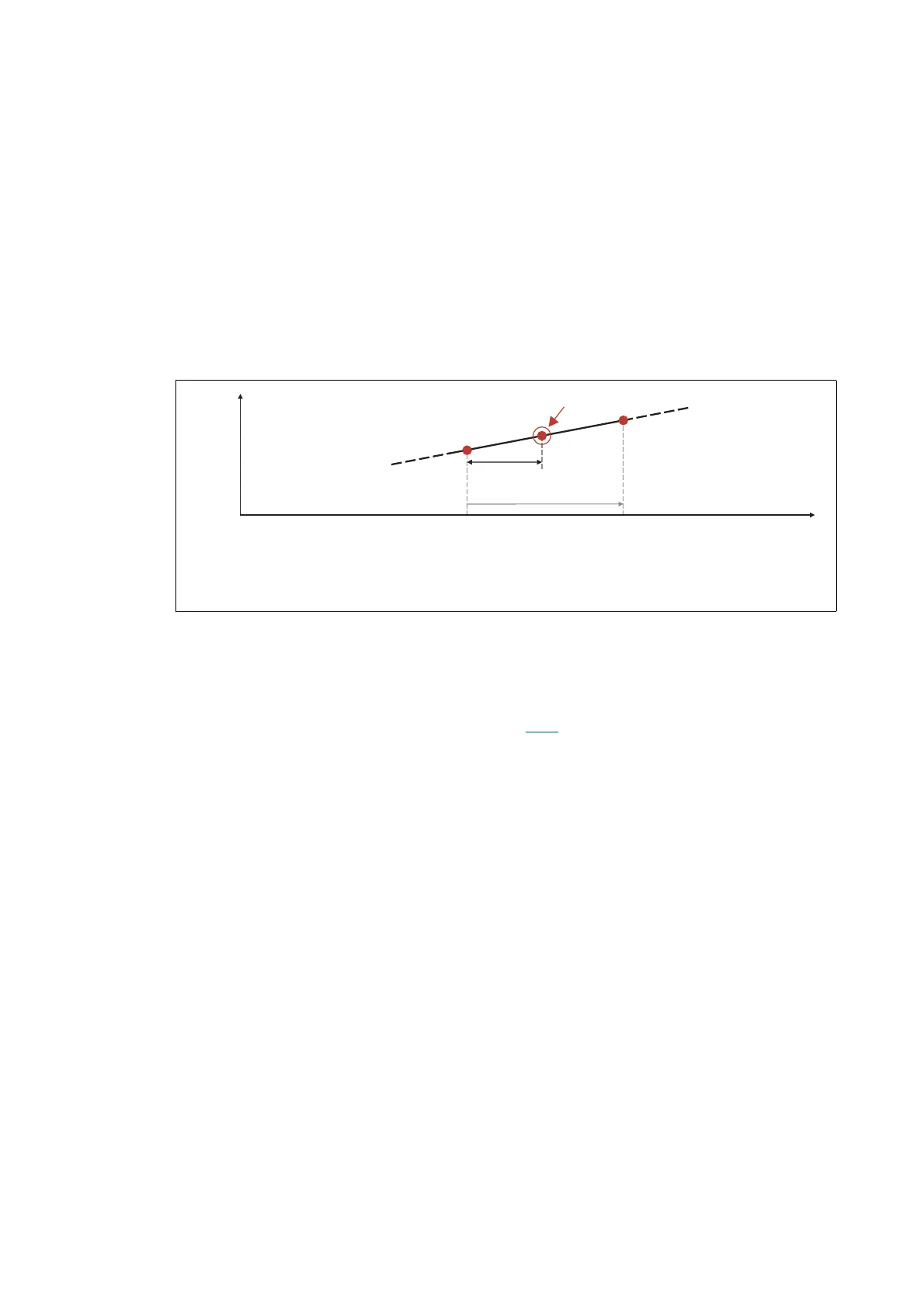
Linear interpolation is executed between these two position grid points. The result is the exact
position at the motor shaft at the time the event is triggered:
[7-9] Determination of the exact position by linear interpolation (principle)
The position grid points are detected in the i700 servo inverter in a grid of 250 μs. After a touch
probe is tripped, the input is deactivated for up to 250 μs in order to avoid bouncing. Thus the
maximum frequency for the tripping of touch probes is 4 kHz.
If, in contrast to the steady motion outlined in figure [7-9]
, an accelerated motion is taken as a basis,
the 250 μs grid also allows for a very good linear position reconstruction, since the velocity change
at the motor shaft can only have a minor effect during 250 μs.
P
n-1
Actual position grid point 1
P
n
Actual position grid point 2
Time difference between the start of the control cycle determined and the actual detection of the event
250 µs
Position
t
t
1
p
n-1
p
n
Event received

 Loading...


