5 Motor control & motor settings
5.11 Setting control loops
115
Lenze · i700 servo inverter · reference manual · DMS 3.0 EN · 06/2016 · TD06
_ _ _ _ _ _ _ _ _ _ _ _ _ _ _ _ _ _ _ _ _ _ _ _ _ _ _ _ _ _ _ _ _ _ _ _ _ _ _ _ _ _ _ _ _ _ _ _ _ _ _ _ _ _ _ _ _ _ _ _ _ _ _ _
5.11 Setting control loops
Subsequent to the motor parameterisation, the different control loops must be set. For quick
commissioning, the calculations and settings can be carried out automatically using the
commissioning functions of the servo inverter. For manual setting, applicable equations are offered
in the following subchapters, too.
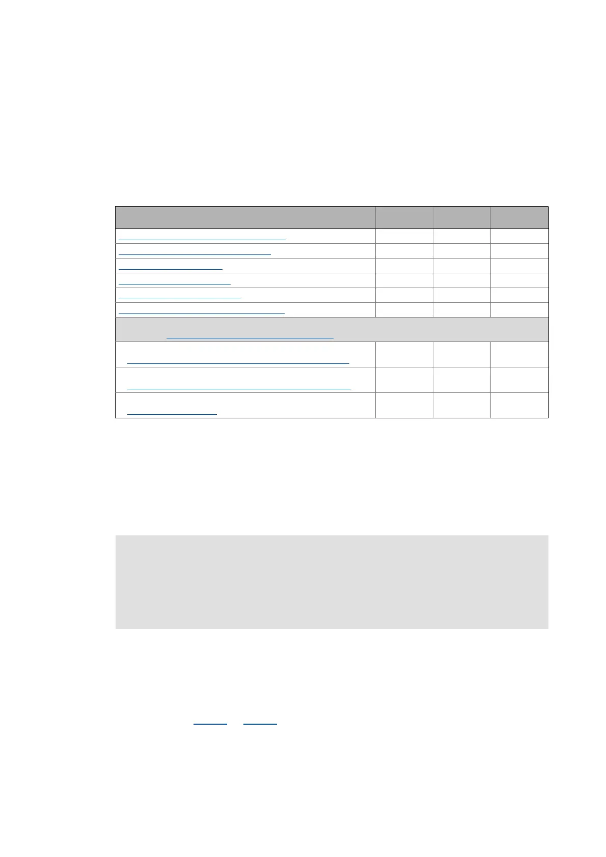
The following table shows the corresponding commissioning steps required for the different
control types and motors:
5.11.1 Setting and optimising the current controller
The control system includes two current controllers, a direct-axis current controller and a cross
current controller, whose parameterisation is carried out identically. The direct-axis current
controller controls the field-producing current (D current). The cross current controller controls the
torque-producing current (Q current). There is a coupling between the two control loops which
makes every actuation of every one of the controllers occur as fault in the control loop of the other
controller. This coupling can be compensated for by activating the current controller feedforward
control via object 0x2941
(or 0x3141 for axis B).
Commissioning step
Servo control
SM
Servo control
ASM
V/f characteristic
control
Setting and optimising the current controller ()()
1
Determining the total moment of inertia
Setting the speed controller
Setting the position controller
Setting the field controller (ASM) ()
Setting the field weakening controller (ASM)
()
Information on the following control loops/commissioning steps for the V/f characteristic control can be found in
the chapter "Parameterising the V/f characteristic control
"
Set Imin controller
Torque increase in the lower speed range ("Boost" function)
Set Imax controller
Defining the behaviour at the current limit (Imax controller)
Set "restart on the fly" controller
"Flying restart" function
Required
() Only required for other manufacturers' motors
1
Only required if voltage vector control, DC-injection braking, or flying restart process is activated.
Note!
For a servo control, the current controller should always be optimised if a motor of
another manufacturer with unknown motor data is used!
For a V/f characteristic control, the current controller only has to be optimised if voltage
vector control is used, or if DC-injection braking or the flying restart process is activated.

 Loading...


