Lenze · i700 servo inverter · reference manual · DMS 3.0 EN · 06/2016 · TD06 190
7 CiA402 device profile
7.4 Device control
_ _ _ _ _ _ _ _ _ _ _ _ _ _ _ _ _ _ _ _ _ _ _ _ _ _ _ _ _ _ _ _ _ _ _ _ _ _ _ _ _ _ _ _ _ _ _ _ _ _ _ _ _ _ _ _ _ _ _ _ _ _ _ _
7.4.2 Device states
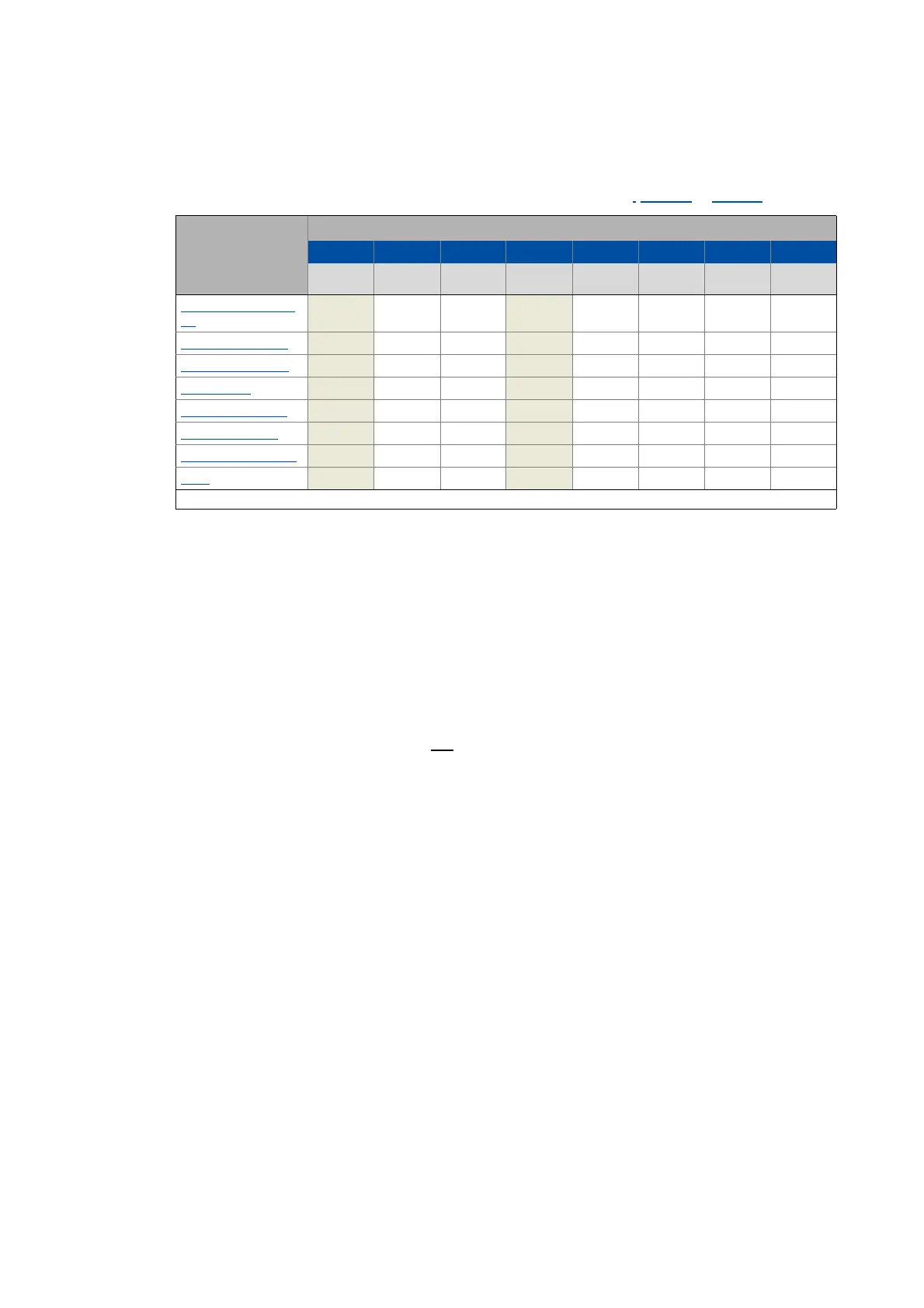
The current device status of the drive can be read via the Statusword (0x6041 or 0x6841 for axis B):
Tip!
Bits 4 ("Voltage enabled") and 7 ("Warning active") are not relevant as regards the device
status and merely serve the purpose of a better readability of the bit patterns here.
Detailed information on the different device states can be obtained from the following
subchapters.
"Warning active" status bit
Via bit 7 in the Statusword, a warning is indicated.
• The occurrence of a warning does not
cause a state change.
• Warnings do not need to be reset.
Device status Bit pattern in the Statusword
Bit 7 Bit 6 Bit 5 Bit 4 Bit 3 Bit 2 Bit 1 Bit 0
Warning is
active
Switch on
disabled
Quick stop Voltage
enabled
Fault active Operation
enabled
Switched on Ready to
switch on
Not ready to switch
on
X0XX0000
Switch on disabled
X1XX0000
Ready to switch on
X01X0001
Switched on
X01X0011
Operation enabled X01X0111
Quick stop active
X00X0111
Fault reaction active
X0XX1111
Fault X0XX1000
X = Status not significant

 Loading...


