Lenze · i700 servo inverter · reference manual · DMS 3.0 EN · 06/2016 · TD06 180
7 CiA402 device profile
7.4 Device control
_ _ _ _ _ _ _ _ _ _ _ _ _ _ _ _ _ _ _ _ _ _ _ _ _ _ _ _ _ _ _ _ _ _ _ _ _ _ _ _ _ _ _ _ _ _ _ _ _ _ _ _ _ _ _ _ _ _ _ _ _ _ _ _
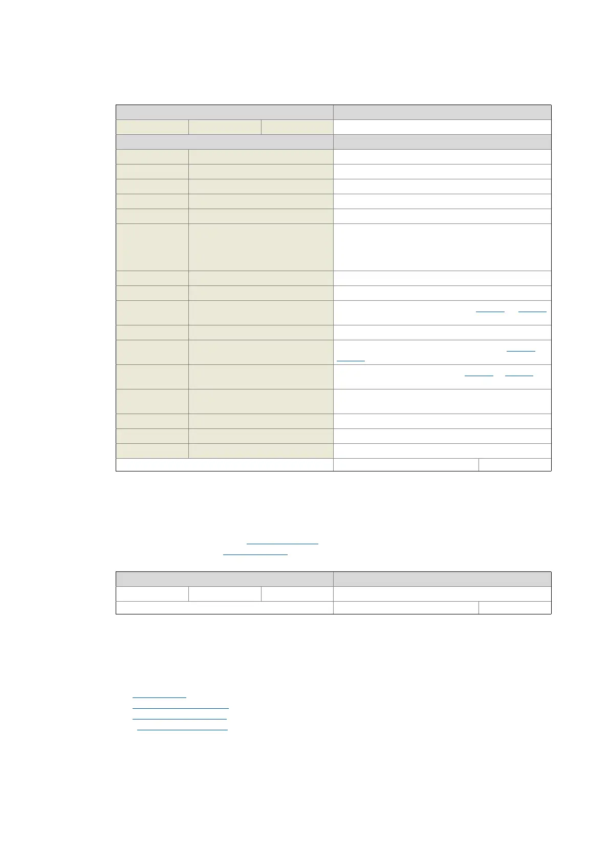
0x605A | 0x685A - Quick stop option code
0x6060 | 0x6860 - Modes of operation
Display area (min. value | unit | max. value) Initialisation
0 65535
Value is bit-coded: Info
Bit 0 Ready to switch on
Bit 1 Switched on
Bit 2 Operation enabled
Bit 3 Trouble active
Bit 4 Voltage enabled
Bit 5 Quick stop If bit 0 ("ready to start") = 1:
• "Quick stop active", bit 4 = 0
• "Quick stop not active", bit 4 = 1
In all other cases, the value of bit 4 is optional.
Bit 6 Switch on disabled
Bit 7 Warning is active
Bit 8 Deactivate RPDOs Cyclic PDOs have been deactivated in 0x2824 (or 0x3024
for axis B).
Bit 9 Remote Drive can receive commands via EtherCAT.
Bit 10 Target reached The actual position is located in the window (0x6067 or
0x6867
for axis B).
Bit 11 Internal limitation is active For details see Lenze status word (0x2831 or 0x3031 for
axis B).
Bit 12 Drive Follows Command Operation is enabled and no test mode is activated (no
internal setpoint generation active).
Bit 13 Following error The position could not be approached.
Bit 14 Brake released
Bit 15 STO is not active
Write access CINH OSC P RX TX UNSIGNED_16
Device status after exiting the quick stop ramp
2 = automatic changeover to the "Switch-on disabled
" device status
6 = the axis remains in the "Quick stop active
" device status.
Setting range (min. value | unit | max. value) Lenze setting
262
Write access CINH OSC P RX TX INTEGER_16
Selection of the operating mode:
0 = no operating mode (standstill)
2 = Velocity mode
8 = Cyclic sync position mode
9 = Cyclic sync velocity mode
10 = Cyclic sync torque mode

 Loading...


