7 CiA402 device profile
7.4 Device control
193
Lenze · i700 servo inverter · reference manual · DMS 3.0 EN · 06/2016 · TD06
_ _ _ _ _ _ _ _ _ _ _ _ _ _ _ _ _ _ _ _ _ _ _ _ _ _ _ _ _ _ _ _ _ _ _ _ _ _ _ _ _ _ _ _ _ _ _ _ _ _ _ _ _ _ _ _ _ _ _ _ _ _ _ _
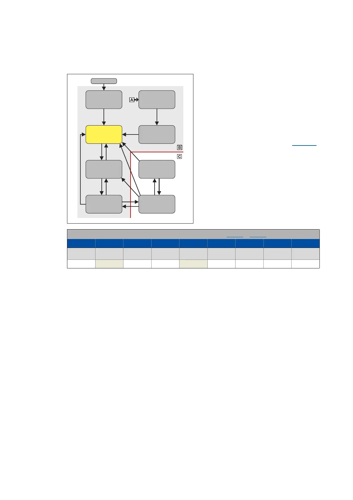
7.4.2.2 Switch on disabled
This is the servo inverter's status after the
device has been initialised successfully.
• The process data monitoring is active.
• Communication is possible.
• DC-bus voltage is available.
• The servo inverter can be parameterised.
• If the internal holding brake control is
active in the i700 servo inverter (0x2820:1
= 0), the motor brake is closed!
• The operation is inhibited.
Bit pattern for the "Switch on disabled" device status in the Statusword (0x6041 or 0x6841 for axis B):
Bits 15 - 8 Bit 7 Bit 6 Bit 5 Bit 4 Bit 3 Bit 2 Bit 1 Bit 0
Warning is
active
Switch on
disabled
Quick stop Voltage
enabled
Fault active Operation
enabled
Switched on Ready to
switch on
X X1XX0000
Ready to
switch on
Not ready to
switch on
Switched
on
Operation
enabled
Fault reaction
active
Fault
active
Switch on
disabled
Quick stop
active
Power on

 Loading...


