8 Monitoring functions
8.7 Motor phase failure monitoring
272
Lenze · i700 servo inverter · reference manual · DMS 3.0 EN · 06/2016 · TD06
_ _ _ _ _ _ _ _ _ _ _ _ _ _ _ _ _ _ _ _ _ _ _ _ _ _ _ _ _ _ _ _ _ _ _ _ _ _ _ _ _ _ _ _ _ _ _ _ _ _ _ _ _ _ _ _ _ _ _ _ _ _ _ _
8.7.2 Monitoring 2: In the "enable operation" state transition
On the basis of test signals, this extended monitoring function for motor phase failure can detect a
phase failure and check the presence of the motor. Only after a successful check, the actual
operation is continued.
• Monitoring is only active for a short time after controller enable (when the device status
changes from "Switched on
" to "Operation enabled") if
• a response other than "0: No response" has been set for this monitoring function in object
0x2D45:4
(or 0x3545:4 for axis B), and
• no test mode and no identification mode (0x2825
or 0x3025 for axis B) are active.
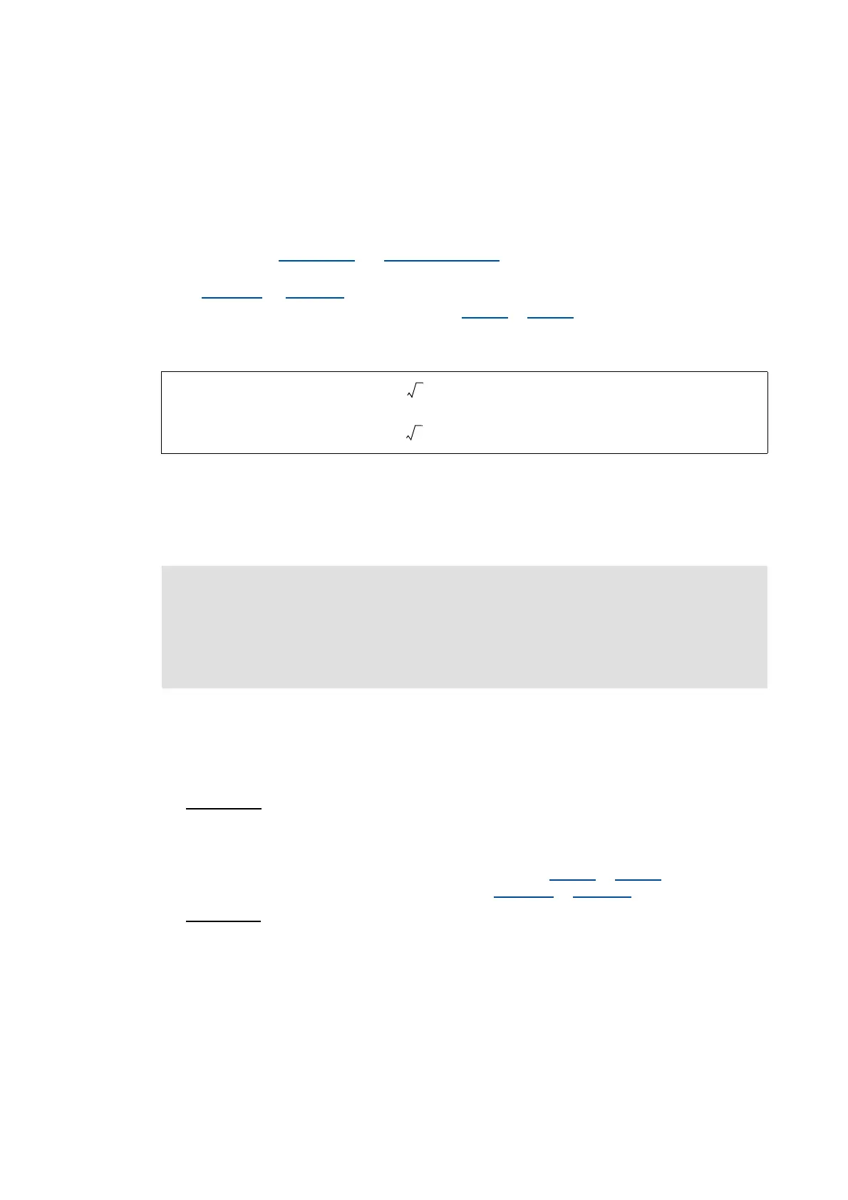
• Before the actual operation, the motor is supplied with a maximum DC current, the max. level
of which corresponds to the lower of the following two values:
• The response set is triggered if one or several motor phase currents have not reached a specific
threshold value within 5 ms after controller enable. The threshold value depends on the
maximum device current and cannot be parameterised.
• The check is completed successfully if all three motor phase currents have exceeded the
threshold value. Then the actual operation is continued immediately.
8.7.3 Monitoring 1: In "operation enabled" status
If a current-carrying motor phase (U, V, W) fails during operation, the response set for this
monitoring is tripped if two conditions are met:
• Condition 1:
Monitoring is activated
• In order to be able to reliably detect the failure of a motor phase, a certain motor current for
the current sensors must flow. The monitoring function therefore is only activated if, in the
case of servo control, the setpoint of the motor current, and in the case of a V/f characteristic
control, the actual value of the motor current (display in 0x6078
or 0x6878 for axis B) has
exceeded a parameterisable current threshold (0x2D45:2
or 0x3545:2 for axis B).
• Condition 2:
A specific commutation angle has been covered without the detection of a current
flow.
• In this case monitoring works according to the principle of checking for each motor phase
that a current flows depending on the commutation angle.
• Monitoring responds if a rotating field is output and hence a specific commutation angle
(approx. 150°, electric) is covered without the current having exceeded a (non-
parameterisable) threshold that depends on the device power.
or
Note!
• As the check is cancelled immediately if all three motor phase currents have exceeded
the threshold value, the setpoint current usually is not achieved.
• In order to be able to achieve the threshold value used for the check, the rated motor
current must at least be 10 % of the maximum device current.
50 % 2 Rated device current⋅⋅
50 % 2 Rated motor current ⋅⋅

 Loading...


