Lenze · i700 servo inverter · reference manual · DMS 3.0 EN · 06/2016 · TD06 284
9 Diagnostics & error management
9.3 History buffer
_ _ _ _ _ _ _ _ _ _ _ _ _ _ _ _ _ _ _ _ _ _ _ _ _ _ _ _ _ _ _ _ _ _ _ _ _ _ _ _ _ _ _ _ _ _ _ _ _ _ _ _ _ _ _ _ _ _ _ _ _ _ _ _
9.3 History buffer
Via the history buffer (0x10F3), the controller can access the last 32 messages of the i700 servo
inverter.
• The history buffer is saved persistently to the i700 servo inverter.
• The structure of the history buffer corresponds to a ring buffer:
• As long as there is free history buffer space available, a message is placed in the next free slot
in the buffer.
• If all buffer slots are full, the oldest message is deleted for a new one.
• The latest messages will always remain available.
• See the "Diag code" (32-bit word) of every single message to find out which axis the message
refers to:
CiA402 error codes / error messages
( 286)
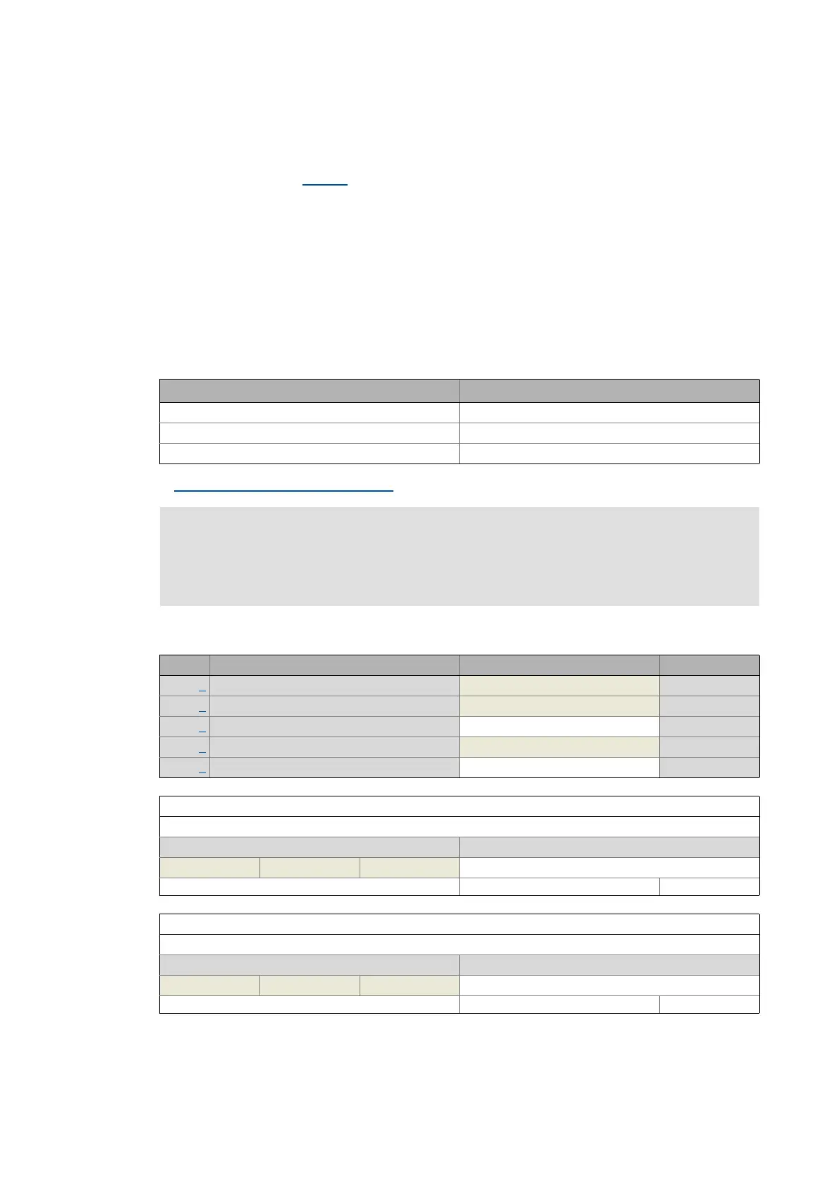
0x10F3 - Diagnostics: History buffer
Diag code bits 0 ... 15 Diag code bits 16 ... 31
0xE000 device error/warning CiA402 error code (device-specific)
0xE001 fault/warning axis A CiA402 error code (axis-specific)
0xE002 fault/warning axis B CiA402 error code (axis-specific)
Document "ETG.1020 Protocol Enhancements"
See chapter 13.3 of document "ETG.1020 Protocol Enhancements" provided by the
EtherCAT Technology Group (ETG) for detailed information on the structure of the
diagnostic messages.
Sub. Name Lenze setting Data type
1 Max. number of messages 32 UNSIGNED_8
2 Latest message 0 UNSIGNED_8
3 Latest acknowledged message 0 UNSIGNED_8
4 New active message 0 UNSIGNED_8
5 Control bits 0 UNSIGNED_16
Subindex 1: Max. number of messages
Maximum number of messages which can be stored in the history buffer (from subindex 6).
Display area (min. value | unit | max. value) Initialisation
0 255 32
Write access CINH OSC P RX TX UNSIGNED_8
Subindex 2: Latest message
Subindex of the most recent message
Display area (min. value | unit | max. value) Initialisation
0 255 0
Write access CINH OSC P RX TX UNSIGNED_8