5 Motor control & motor settings
5.3 Wiring check by means of manual test modes
67
Lenze · i700 servo inverter · reference manual · DMS 3.0 EN · 06/2016 · TD06
_ _ _ _ _ _ _ _ _ _ _ _ _ _ _ _ _ _ _ _ _ _ _ _ _ _ _ _ _ _ _ _ _ _ _ _ _ _ _ _ _ _ _ _ _ _ _ _ _ _ _ _ _ _ _ _ _ _ _ _ _ _ _ _
Preconditions for the execution
• The motor must be able to rotate freely.
• The servo inverter is free of errors and is in the "Switched on
" device status.
Response of the motor during the execution
The motor rotates as a function of the set output frequency.
How to activate the manual test mode "voltage/frequency":
1. If the servo inverter is enabled, inhibit the servo inverter.
Enable/inhibit operation via control word
( 52)
2. Set object 0x2825
(or 0x3025 for axis B) to "1" to change to the "Voltage/frequency" test
mode.
3. Enable the servo inverter to start the test mode.
4. To stop the test mode:
• Inhibit the servo inverter.
•Set object 0x2825
(or 0x3025 for axis B) to "0" to change back to the CiA402 mode.
5.3.2 Manual test mode "current/frequency"
Functional description
In this test mode, three phase currents are injected in the connected motor after controller enable.
• Via the following objects, the test mode can be adapted:
• The current phase currents can be read via the following objects:
Advantages compared to the manual test mode "voltage/frequency":
• The current does not set freely, but is controlled to a defined value.
• If a synchronous motor is connected, the generated torque can be predicted.
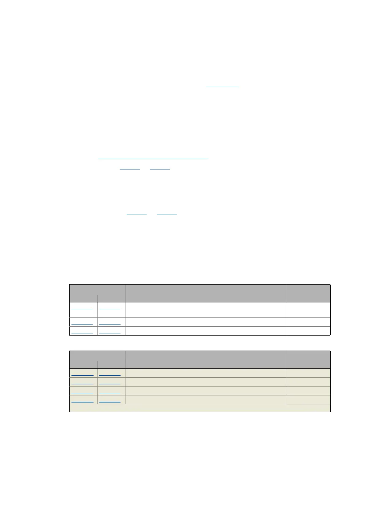
Object Info Data type
Axis A Axis B
0x2835:1 0x3035:1 r.m.s. value of a phase current
• Selection in [%] relative to the rated motor current.
INTEGER_16
0x2835:2
0x3035:2 Frequency INTEGER_16
0x2835:3
0x3035:3 Starting angle INTEGER_16
Object Info Data type
Axis A Axis B
0x2D83:1 0x3583:1 Motor current zero system INTEGER_32
0x2D83:2 0x3583:2 Motor current phase U INTEGER_32
0x2D83:3 0x3583:3 Motor current phase V INTEGER_32
0x2D83:4 0x3583:4 Motor current phase W INTEGER_32
Greyed out = read access only

 Loading...


