Lenze · i700 servo inverter · reference manual · DMS 3.0 EN · 06/2016 · TD06 222
7 CiA402 device profile
7.8 Cyclic sync position mode (csp)
_ _ _ _ _ _ _ _ _ _ _ _ _ _ _ _ _ _ _ _ _ _ _ _ _ _ _ _ _ _ _ _ _ _ _ _ _ _ _ _ _ _ _ _ _ _ _ _ _ _ _ _ _ _ _ _ _ _ _ _ _ _ _ _
Tip!
A detailed representation of the signal flow with all relevant parameters can be found in
the »PLC Designer« on the Signal flow tab for the i700 servo inverter.
7.8.4 Control commands & status information
The following control commands can be executed in cyclic sync position mode via the Controlword
(0x6040
or 0x6840 for axis B):
The following status information is output in cyclic sync position mode via the Statusword (0x6041
or 0x6841 for axis B):
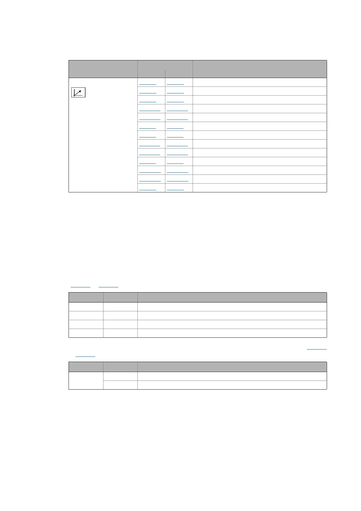
Field-oriented control 0x6073 0x6873 Max current
0x6075
0x6875 Motor rated current
0x2941
0x3141 Current controller: Feedforward control
0x2942:1
0x3142:1 Current controller: Gain
0x2942:2
0x3142:2 Current controller: Reset time
0x29E2
0x31E2 DC link circuit voltage: Filter time
0x29E3
0x31E3 Motor voltage act. value: Filter time
0x29E0:1
0x31E0:1 Field weakening controller: Gain
0x29E0:2
0x31E0:2 Field weakening controller: Reset time
0x29E1
0x31E1 Field set value limitation
0x29C0:1
0x31C0:1 Field controller: Gain
0x29C0:2
0x31C0:2 Field controller: Reset time
0x2939
0x3139 Switching frequency
Function Object Name
Axis A Axis B
Control word Status Function
Bit 4 0 Reserved (bit must be set to "0")
Bit 5 0 Reserved (bit must be set to "0")
Bit 6 0 Reserved (bit must be set to "0")
Bit 8 0 1Stop
Status word Status Meaning
Bit 12 0 Cyclic sync position mode inactive
1 Cyclic sync position mode active
 Loading...


